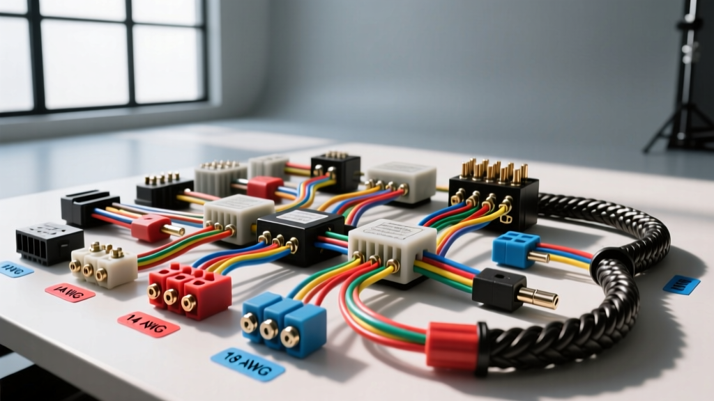
Understanding the Automotive Wire Gauge Chart
Selecting the correct wire size is the most critical step in any automotive electrical project. An undersized wire will overheat, cause excessive voltage drop, and potentially start a fire, while an oversized wire adds unnecessary weight, stiffness, and cost to a wiring harness. Unlike household wiring, automotive electrical systems operate in a harsh 12V-14V DC environment characterized by high vibration, extreme temperature fluctuations, and exposure to corrosive fluids.
The American Wire Gauge (AWG) system is the standard used in North America for automotive wiring. In the AWG system, a smaller gauge number indicates a larger, thicker wire with lower electrical resistance. For professional automotive applications, it is imperative to follow the SAE J1128 standard, which dictates the physical dimensions, insulation types, and thermal ratings for low-tension automotive primary cables.
Primary Wire Gauge Chart: Ampacity & Resistance
The following automotive wire gauge chart details the specifications for standard stranded copper wire. The ampacity ratings listed below are based on chassis wiring (single conductor in free air under the hood or inside the cabin), not power transmission wiring (bundled in tight looms or enclosed spaces). When wires are bundled together, their ability to dissipate heat decreases, requiring you to derate the ampacity by 20% to 30%.
| AWG Size | Stranding | Circular Mils | Nominal O.D. (in) | Resistance (Ω/1000ft @ 20°C) | Max Ampacity (Chassis) |
|---|---|---|---|---|---|
| 18 | 16/30 | 1,600 | 0.068 | 6.385 | 16A |
| 16 | 26/30 | 2,580 | 0.079 | 4.016 | 22A |
| 14 | 41/30 | 4,110 | 0.092 | 2.525 | 32A |
| 12 | 65/30 | 6,530 | 0.112 | 1.588 | 41A |
| 10 | 105/30 | 10,380 | 0.138 | 0.9989 | 55A |
| 8 | 133/29 | 16,510 | 0.169 | 0.6282 | 73A |
| 6 | 133/27 | 26,240 | 0.211 | 0.3951 | 101A |
| 4 | 133/25 | 41,740 | 0.260 | 0.2485 | 135A |
Note: Always size your inline fuses or circuit breakers based on the wire's ampacity rating, not the load's maximum draw. The fuse is there to protect the wire from melting.
AWG vs. Metric (mm²) Conversion for Modern Vehicles
If you are repairing or modifying a late-model European (BMW, Audi, Porsche) or Asian (Toyota, Honda, Nissan) vehicle, you will encounter metric wiring measured in square millimeters (mm²) rather than AWG. Splicing AWG wire into a metric harness can lead to mechanical crimp failures if the terminal sizes are mismatched. Below is the standard conversion chart used by OEM harness manufacturers.
- 0.50 mm² (approx. 20 AWG): Used for CAN bus networks, low-current sensors (e.g., O2 sensor signal wires), and ECU data lines.
- 0.75 mm² (approx. 18 AWG): Standard for fuel injectors, ignition coil triggers, and low-draw LED lighting circuits.
- 1.50 mm² (approx. 16 AWG): Common for interior lighting, power seat logic, and horn circuits.
- 2.50 mm² (approx. 14 AWG): Utilized for power windows, door lock actuators, and blower motor speed controls.
- 4.00 mm² (approx. 11 AWG): High-draw lighting, auxiliary fuel pumps, and cooling fan relays.
- 6.00 mm² (approx. 10 AWG): Main ECU power feeds, high-output alternator sense wires, and primary fuel pump feeds.
Application-Specific Wiring Guidelines
Understanding the wire gauge chart is only half the battle. Real-world automotive applications require accounting for inrush currents, duty cycles, and environmental factors.
High-Pressure EFI Fuel Pumps
Modern brushless or high-flow fuel pumps (such as the Walbro 450lph or AEM 340) have massive inrush currents that can spike to 25A-30A for the first 200 milliseconds before settling at a running current of 12A-15A. For a standard trunk-mounted fuel cell with a 12-foot run to the front engine bay:
- Main Feed: Use 10 AWG TXL wire from the battery to a 40A Bosch-style relay (Terminal 30).
- Relay to Pump: Use 12 AWG GXL wire from the relay (Terminal 87) to the fuel pump hanger.
- Connectors: Terminate the pump side with a pigtail utilizing Metri-Pack 280 series female terminals. Crimp using a ratcheting tool. Never solder under-hood or under-car fuel pump connections; solder wicks into the stranded wire, creating a rigid point that will inevitably snap under chassis vibration.
Electric Cooling Fans
Dual 11-inch SPAL fans can pull a combined 35A+ at startup. Running both fans on a single 10 AWG wire will result in severe voltage drop at the fan motors, reducing their RPM and cooling efficiency.
- Solution: Run an 8 AWG main feed to a heavy-duty relay block or fuse panel mounted near the radiator core support. From the block, split the circuit using two separate 12 AWG wires, each feeding its own 30A relay dedicated to one fan.
CAN Bus and Sensor Networks
For late-model engine swaps utilizing OEM ECUs, the Controller Area Network (CAN) bus is critical. CAN-H and CAN-L lines typically use 0.50 mm² (20 AWG) wire. These wires must be twisted together (at least 1 twist per inch) to reject Electromagnetic Interference (EMI) from the alternator and ignition coils. Use shielded twisted pair (STP) cable if the harness must be routed near high-voltage ignition coils or aftermarket CDI boxes.
Voltage Drop Calculations for Long Harness Runs
The wire gauge chart provides resistance per 1,000 feet. In a vehicle, long runs (like trailer wiring or rear-mounted batteries) require voltage drop calculations to ensure the end component receives adequate voltage. The formula for a DC circuit is:
Voltage Drop (VD) = (2 × L × R × I) / 1000
- L = One-way length of the wire in feet
- R = Resistance per 1000ft (from the chart)
- I = Current (Amps)
Real-World Example: You are wiring an electronic trailer brake controller mounted in the dash, but the power feed is routed 20 feet to the rear bumper to a 7-way trailer plug (40 feet total round trip). The trailer pulls 12 Amps under heavy braking. If you use 14 AWG wire (2.525 Ω/kft):
VD = (2 × 20 × 2.525 × 12) / 1000 = 1.21 Volts.
If the alternator is outputting 14.2V, the trailer plug receives 12.99V, which is perfectly acceptable. However, if you mistakenly used 18 AWG wire (6.385 Ω/kft), the drop would be 3.06 Volts, leaving the trailer with only 11.14V, which can trigger undervoltage fault codes and result in weak braking performance.
Insulation Types: Why PVC is for Houses, Not Cars
When sourcing wire from suppliers like Del City Wire or Painless Performance, you will notice different insulation prefixes. Never use standard THHN or MTW (PVC-insulated) wire in an automotive engine bay. PVC insulation melts at relatively low temperatures, becomes brittle in cold weather, and off-gasses toxic chlorine gas when it contacts hot exhaust manifolds.
Always specify Cross-Linked Polyethylene (XLPE) automotive wire:
- GXL (General Cross-Linked): 125°C rating. Standard thin-wall insulation. Ideal for general chassis and engine bay routing.
- TXL (Thin Cross-Linked): 125°C rating. Extra thin wall. Best for building custom harnesses that must pass through tight firewall grommets or modern, dense connector cavities.
- SXL (Special Cross-Linked): 125°C rating. Standard/thick wall. Use this for areas prone to high abrasion, such as frame rails, suspension pickups, or anywhere the wire is exposed to road debris.
Common Failure Modes from Incorrect Gauge Selection
- Thermal Runaway at Connectors: Using 16 AWG wire on a 20A circuit may not immediately melt the wire, but the constant heat generation will degrade the brass terminals inside the connector. This increases contact resistance, which generates more heat, eventually melting the plastic connector housing (a very common failure in aftermarket headlight harnesses).
- ECU Reset/Reboot Issues: Undersized ground wires (e.g., using 14 AWG for a main ECU ground instead of 10 AWG) will cause the ground potential to float under high load. When the fuel injectors fire simultaneously, the voltage spike on the ground plane can cause the ECU to read sensor data incorrectly or reboot entirely.
- Alternator Whine in Audio Systems: Using undersized power or ground wire for high-draw amplifiers forces the amplifier to pull current inconsistently, modulating the system voltage and introducing alternator whine into the RCA signal grounds.
By strictly adhering to this automotive wire gauge chart and understanding the thermal and physical limitations of your chosen conductors, you can build a reliable, safe, and professional-grade electrical system capable of surviving the harsh realities of the automotive environment.