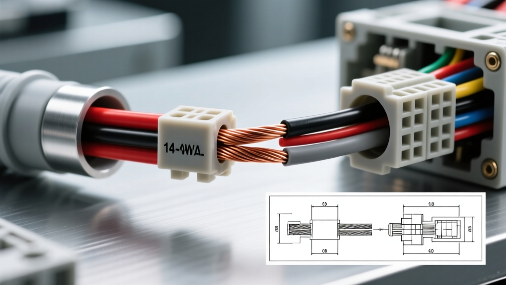
The Baseline: SAE J1128 vs. NEC Ampacity Standards
When engineering automotive electrical systems, misunderstanding the 14 gauge wire amperage rating is one of the most common pitfalls for novice builders and even seasoned mechanics. In residential and commercial construction, the National Electrical Code (NEC) Article 240 strictly limits 14 AWG copper wire to a 15-ampere continuous load. However, applying this NFPA 70 NEC standard to a 12-volt DC automotive chassis environment is fundamentally incorrect and leads to massively oversized, heavy, and inflexible wiring harnesses.
Automotive wiring is governed by the SAE J1128 standard, which evaluates ampacity based on single wires in free air, high-temperature cross-linked insulations, and 12V/24V DC systems. Under SAE J1128, a single 14 AWG wire with high-temperature insulation (like TXL or GXL) can safely carry between 20 and 25 amps in a 20°C ambient environment. The discrepancy arises because automotive chassis wiring relies on the vehicle's metal frame for grounding (reducing heat buildup compared to bundled Romex) and utilizes advanced thin-wall insulations that can withstand significantly higher thermal thresholds than standard 60°C PVC.
Insulation Types and Thermal Derating Factors
The true current-carrying capacity of 14 AWG wire is dictated not by the copper itself, but by the thermal limits of its insulation. In modern EFI and CAN-bus vehicle architectures, you will primarily encounter three types of cross-linked polyethylene (XLPE) automotive wire:
- TXL (Thin-wall): Rated for 125°C. Standard for most under-dash and engine bay sensor harnesses.
- GXL (General-wall): Rated for 125°C, slightly thicker insulation for abrasion resistance.
- SXL (Special-wall): Rated for 150°C. Used in high-heat zones like exhaust-proximate O2 sensor feeds or turbocharger oil scavenge pumps.
As ambient under-hood temperatures rise, the 14 gauge wire amperage rating must be derated to prevent insulation melting or off-gassing. The following table illustrates the derating curve for a single 14 AWG TXL wire in free air:
| Ambient Temp (°C) | Derating Factor | Adjusted Max Ampacity (14 AWG TXL) |
|---|---|---|
| 20°C (68°F) | 100% | 25.0 Amps |
| 40°C (104°F) | 90% | 22.5 Amps |
| 60°C (140°F) | 75% | 18.7 Amps |
| 80°C (176°F) | 58% | 14.5 Amps |
| 100°C (212°F) | 40% | 10.0 Amps |
| 125°C (257°F) | 0% | 0 Amps (Insulation Limit) |
Note: If wiring is bundled into a loom or conduit with more than three current-carrying conductors, an additional 20% derating penalty must be applied to the values above.
Voltage Drop Calculations in 14 AWG Automotive Circuits
Amperage rating is only half the engineering equation; voltage drop is the other. 14 AWG copper wire possesses a nominal resistance of 2.525 ohms per 1,000 feet at 20°C. In a 12-volt nominal system (often 13.8V to 14.4V at the alternator), excessive resistance starves sensitive ECU drivers and fuel injectors of the voltage required to operate efficiently.
Consider an auxiliary LED light bar relay trigger circuit. The run from the cabin switch, through the firewall, to the engine bay relay is 12 feet. The relay coil draws 0.25 amps. The voltage drop is negligible. However, if you attempt to use 14 AWG to power a pair of 55W H4 halogen headlights directly from a firewall-mounted relay (10-foot round trip, 9.1 amps total), the math changes:
Formula: Voltage Drop = (2 × Length × Current × Resistance per 1000ft) / 1000
Calculation: (2 × 5 × 9.1 × 2.525) / 1000 = 0.23 Volts.
A 0.23V drop is well within the acceptable 3% limit (0.42V on a 14V system) for lighting circuits. However, if that same 14 AWG wire was used for a 20-amp electric cooling fan, the drop would be 0.50V, pushing the boundaries of acceptable efficiency and generating excess heat in the wire.
Real-World Scenario: GM LS Fuel Pump Relay Control Circuit
To understand how the 14 gauge wire amperage rating applies to modern EFI swaps, let us examine the fuel pump relay control circuit in a GM LS1/LS2 Powertrain Control Module (PCM) harness. The PCM does not power the fuel pump directly; it switches the ground path for the relay coil.
- Connector: Delphi Metri-Pack 280 Series (Female Terminal)
- PCM Pinout: Connector C2 (Blue), Pin 12
- Wire Color: Dark Green (GM standard for FP relay control)
- Circuit Load: Standard Bosch-style 12V relay coil (approx. 75 ohms, drawing ~0.16 Amps).
While the PCM driver only sees 0.16 amps, the wiring from the ignition switch (Pink wire, 12V+ in Run/Start) to the relay Pin 86, and the relay Pin 85 to the PCM C2-12, is typically manufactured in 14 AWG or 16 AWG by the OEM. Why use 14 AWG for a 0.16A load? Mechanical durability. The engine harness is subjected to severe vibration, thermal cycling, and abrasion. 14 AWG provides the necessary tensile strength and copper mass to survive a 15-year service life without fatigue-fracturing at the crimp terminal.
Conversely, the load side of the relay (Pin 30 to Pin 87) feeding a Walbro 255lph fuel pump must be upgraded to 12 AWG or 10 AWG, as the pump draws 12 to 15 amps continuously under load, and voltage drop at the pump directly reduces fuel flow volume.
Terminal Crimping and USCAR Failure Modes
Rating a wire is useless if the termination fails. For 14 AWG (2.0mm²) automotive circuits, the industry standard is the Aptiv (formerly Delphi) Metri-Pack 280 or TE Connectivity AMP Superseal 1.5 series. Proper crimping requires a precision ratcheting crimper calibrated to USCAR-21 specifications.
A valid 14 AWG crimp must exhibit the following characteristics:
- Wire Crimp Height: Typically 1.15mm to 1.25mm, depending on the terminal plating and base metal.
- Bellmouth: A visible rear bellmouth (0.25mm to 0.50mm) to prevent the sharp terminal edge from shearing copper strands during vibration.
- Pull-Out Force: SAE/USCAR standards mandate a minimum tensile pull-out force of 150 Newtons (33.7 lbf) for 2.0mm² terminals. If your terminal slips out before reaching this threshold, your crimp die is worn or improperly adjusted.
Capillary Action and Galvanic Corrosion
The most common failure mode in 14 AWG engine bay wiring is moisture ingress via capillary action. If a crimp is performed without an adhesive-lined heat shrink sleeve (or if the terminal seal plug is missing in a Metri-Pack connector), moisture wicks between the copper strands. This leads to galvanic corrosion, turning the copper into high-resistance copper oxide. A circuit that originally drew 12 amps through a pristine 14 AWG wire will suddenly experience a localized voltage drop at the corrosion site, generating intense heat and eventually melting the connector housing.
Metallurgy: Oxygen-Free Copper (OFC) vs. Copper-Clad Aluminum (CCA)
When sourcing 14 AWG wire for high-performance automotive builds, metallurgy matters. Cheap aftermarket harness kits often utilize Copper-Clad Aluminum (CCA). While CCA weighs less, aluminum has only 61% of the conductivity of pure copper. Therefore, a 14 AWG CCA wire effectively performs like a 16 AWG OFC wire in terms of resistance and voltage drop, completely invalidating the standard 14 gauge wire amperage rating. Always verify that your spool is stamped with SAE J1128 and specifies pure OFC or bare copper stranding (typically 19 strands of 0.37mm wire) to ensure the harness can safely handle the thermal and electrical demands of modern alternators and EFI systems.