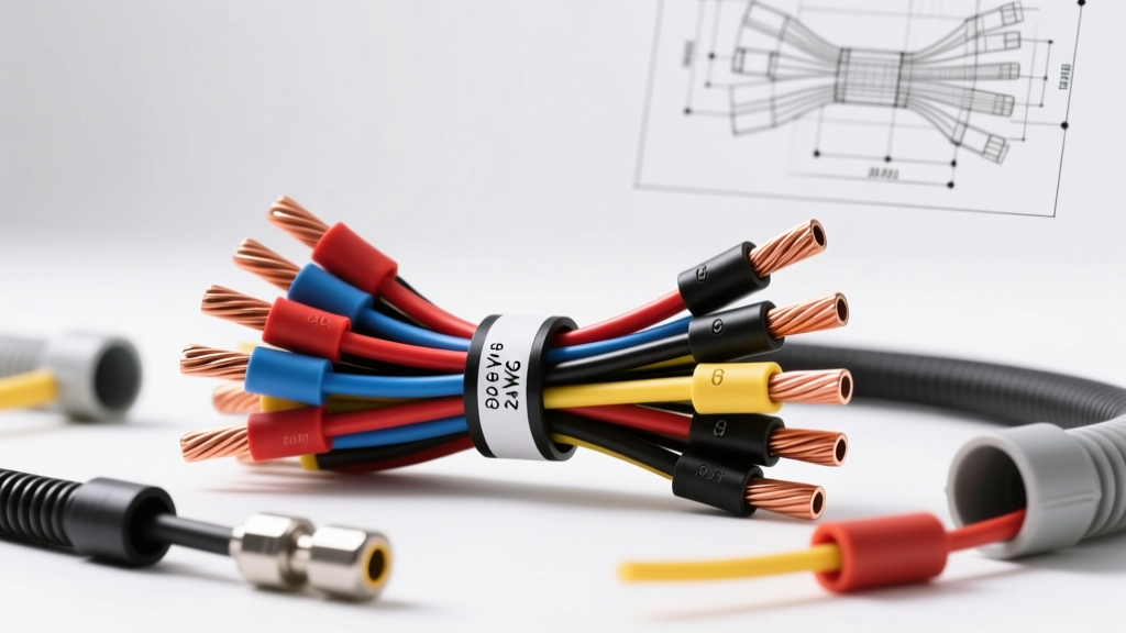
The Physics of 24V Architecture in Heavy-Duty & EV Systems
Transitioning from a standard 12V automotive architecture to a 24V DC system fundamentally alters the engineering requirements for wire gauge selection. In Class 8 heavy-duty trucks (such as the Peterbilt 579 and Kenworth T680), military platforms (HMMWV, FMTV), and large marine vessels, 24V systems are utilized to reduce current draw for high-wattage loads. According to Joule's Law and the power equation (P = I × V), doubling the system voltage halves the current required to deliver the same wattage. For example, a 3,600W starter motor draws roughly 300A on a 12V system, but only 150A on a 24V system.
While this halving of current theoretically allows engineers to downsize wire gauges, high-ambient temperature environments and strict voltage drop tolerances dictate that 24V wire gauge sizing must be calculated using advanced derating matrices. A miscalculation in a 24V heavy-duty application leads to excessive voltage drop, premature insulation breakdown, and catastrophic failure of sensitive Engine Control Modules (ECMs) and multiplexed power distribution boards.
Comprehensive 24V Wire Gauge & Ampacity Matrix
The following matrix is engineered for chassis and engine bay routing in 24V DC systems. Ampacity ratings are based on copper conductors with Cross-Linked Polyethylene (XLPE) insulation, compliant with SAE J1128 Low Tension Primary Cable Standards. Engine bay ratings apply a 125°C ambient temperature derating factor of 0.75.
| AWG Size | Metric (mm²) | Resistance (Ω/1000ft) | Chassis Ampacity (40°C) | Engine Bay Ampacity (125°C) | Common 24V Application |
|---|---|---|---|---|---|
| 4/0 AWG | 107.2 mm² | 0.0490 | 380A | 285A | Main Battery Bank to Starter Solenoid |
| 2/0 AWG | 67.4 mm² | 0.0779 | 320A | 240A | 24V Alternator B+ Output, Heavy Winches |
| 1/0 AWG | 53.5 mm² | 0.0983 | 260A | 195A | Main Power Distribution Busbars |
| 2 AWG | 33.6 mm² | 0.1563 | 210A | 157A | Air Compressor Motors, Liftgate Hydraulics |
| 4 AWG | 21.1 mm² | 0.2485 | 160A | 120A | High-Output Inverter Inputs (24V to 120V AC) |
| 8 AWG | 8.36 mm² | 0.6282 | 100A | 75A | HVAC Blower Motors, PTO Controllers |
| 12 AWG | 3.31 mm² | 1.5880 | 40A | 30A | Fuel Heaters, 24V Lighting Relays |
| 16 AWG | 1.31 mm² | 4.0160 | 18A | 13A | ECM Sensor Feeds, CAN-Bus Power |
Voltage Drop Engineering: 12V vs. 24V Systems
The acceptable voltage drop limit for continuous heavy-duty circuits is generally 2% to 3%. In a 12V system, a 3% drop equates to an absolute loss of 0.36V. In a 24V system, a 3% drop allows for an absolute loss of 0.72V. This doubled absolute tolerance is a critical advantage in long-wheelbase trucks and marine applications, allowing for extended wire runs without stepping up the wire gauge.
Use the following formula to calculate exact voltage drop: VD = (2 × L × I × R) / 1000, where L is one-way length in feet, I is current in amps, and R is resistance per 1000ft of the selected wire gauge.
Voltage Drop Comparison Matrix (40A Load, 20ft One-Way Run)
| Wire Gauge | Resistance (Ω/1000ft) | Absolute Voltage Drop | % Drop on 12V System | % Drop on 24V System | Engineering Verdict |
|---|---|---|---|---|---|
| 8 AWG | 0.6282 | 1.005V | 8.37% (FAIL) | 4.18% (Marginal) | Reject for 12V; Acceptable for non-critical 24V |
| 6 AWG | 0.3951 | 0.632V | 5.26% (FAIL) | 2.63% (PASS) | Ideal for 24V continuous 40A loads |
| 4 AWG | 0.2485 | 0.397V | 3.31% (Marginal) | 1.65% (PASS) | Required for 12V; Overkill for 24V |
Insulation Standards and Connector Specifications
Selecting the correct 24V wire gauge is only half the engineering challenge; the insulation chemistry and termination hardware must withstand high-vibration, high-heat environments. Standard PVC insulation melts and becomes brittle in modern engine bays. For 24V heavy-duty applications, specify XLPE (Cross-Linked Polyethylene) or TXL/GXL wire, which maintains dielectric integrity up to 150°C.
For harness terminations, avoid standard open-barrel crimps. Utilize MIL-DTL-22520G spec indent crimping tools with closed-barrel, environmental-sealed connectors. The Deutsch DT and DTM series are the industry standard for 24V sensor and actuator networks, rated for 250V DC and featuring silicone rear seals that prevent moisture wicking into the copper strands. When terminating high-amperage 2/0 AWG or 4/0 AWG battery cables to Delco-Remy 50MT starters, use hex-crimp copper lugs (e.g., Burndy YAV series) and torque the M10 terminal hardware to exactly 15-20 Nm (11-15 lb-ft) using a calibrated torque wrench to prevent thermal runaway at the lug interface.
Real-World Application: Class 8 Truck 24V Alternator Circuit
When wiring a high-output 24V alternator, such as the Delco-Remy 55SI (rated up to 120A at 24V), specific gauge and pinout protocols must be followed to ensure proper voltage regulation and prevent battery boiling.
- B+ Output Terminal: Requires 2/0 AWG XLPE cable (Red) routed directly to the main battery bank positive busbar. Do not route through intermediate junction blocks to minimize resistance.
- Pin 1 (Excite/Ignition): Requires 14 AWG wire (Yellow). Carries minimal current but must be sourced from a clean, switched 24V ignition bus to wake the internal regulator.
- Pin 2 (Remote Voltage Sense): Requires 10 AWG wire (White). This is the most critical diagnostic circuit. The sense wire must be fused at 10A and routed directly to the farthest positive battery terminal. If undersized (e.g., using 18 AWG), voltage drop across the sense wire will trick the regulator into overcharging the 24V battery bank, pushing system voltage past 29.5V and destroying fleet telematics modules.
For comprehensive marine and heavy-duty routing guidelines, engineers should cross-reference ABYC E-11 AC and DC Electrical Systems on Boats, which provides strict tables for 24V DC voltage drop limits in saltwater environments where corrosion accelerates resistance.
Advanced Troubleshooting: High-Resistance Failure Modes
When diagnosing 24V electrical faults, technicians frequently mistake a failing component for a bad wire gauge or poor termination. Use the following diagnostic protocol to isolate high-resistance faults in 24V heavy-duty circuits:
- Perform Loaded Voltage Drop Testing: Never test resistance with an ohmmeter on a live 24V heavy-duty circuit. Instead, connect a digital multimeter (DMM) in parallel across the suspected wire or connection while the circuit is under full load (e.g., cranking the engine). A voltage drop reading greater than 0.1V per connection point indicates a failing crimp or corroded lug.
- Thermal Imaging Analysis: Utilize a FLIR thermal camera to scan the power distribution board and starter solenoid under load. A poorly crimped 4/0 AWG lug carrying 150A will exhibit a heat signature 30°C to 50°C above ambient within 30 seconds of cranking. This thermal expansion and contraction cycle eventually loosens the M10 terminal nut, leading to arcing.
- Strand Corrosion Inspection: In 24V military and marine applications, capillary action can draw saltwater deep into the wire jacket. Strip back 2 inches of insulation near the termination. If the copper strands exhibit a green/black patina (copper oxide/sulfate), the entire wire run must be replaced. Cleaning the visible tip will not restore the ampacity of the corroded internal strands, effectively reducing a 2/0 AWG cable to the current-carrying capacity of an 8 AWG wire.
Proper 24V wire gauge selection requires balancing ampacity limits, thermal derating, and absolute voltage drop tolerances. By adhering to SAE standards and utilizing heavy-duty termination practices, fleet engineers can ensure maximum uptime and electrical reliability in the most demanding operational environments. For further technical data on overcurrent protection, consult the Littelfuse Automotive Application Notes for time-current curve matching with your selected wire gauges.