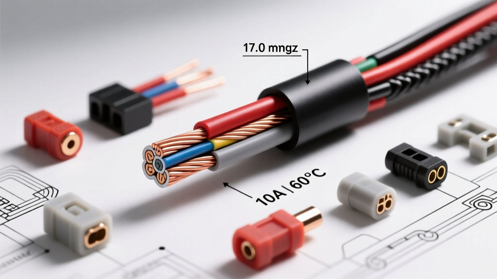
Introduction to 17 Gauge Wire in Automotive Systems
When beginners enter the world of automotive wiring, they typically gravitate toward standard even-numbered gauges like 16, 14, or 12 AWG for power and ground circuits. However, 17 gauge wire occupies a critical, often misunderstood niche in modern vehicle harnesses. While it is an "odd" gauge in the American Wire Gauge (AWG) system, 17 AWG serves as the exact mathematical bridge to the metric 1.0 mm² standard mandated by ISO 6722 and DIN 72551 for European and late-model domestic vehicles.
Understanding 17 gauge wire is essential for anyone working on modern Controller Area Network (CAN) bus systems, low-current sensor circuits, and precision solenoids. Using a wire that is too thick (like 16 AWG) can damage micro-connector cavities, while a wire that is too thin (like 18 AWG) can introduce unacceptable voltage drops over long harness runs. This guide breaks down the fundamental specifications, real-world applications, and termination best practices for 17 AWG wire in automotive environments.
17 AWG Technical Specifications Chart
The physical and electrical properties of 17 AWG wire make it uniquely suited for low-amperage, high-reliability signaling. The following chart outlines the core specifications based on standard bare copper conductors at 20°C (68°F), referencing Belden's standard wire gauge charts and SAE J1128 Low Tension Primary Cable standards.
| Property | Specification | Automotive Context |
|---|---|---|
| AWG Size | 17 AWG | Odd-number gauge, less common in aftermarket kits but standard in OEM harnesses. |
| Diameter (Inches) | 0.0453 in | Allows for tight bending radii in complex dashboard and engine bay looms. |
| Diameter (Millimeters) | 1.15 mm | Matches metric terminal crimp barrels designed for 1.0 mm² to 1.5 mm² wire. |
| Cross-Sectional Area | 1.038 mm² | Effectively equivalent to the European 1.0 mm² metric wire standard. |
| Resistance (Ω / 1000 ft) | 5.21 Ohms | Low enough to maintain 5V reference signals over 20+ foot runs without degradation. |
| Max Ampacity (Chassis Wiring) | ~5.0 Amps | Ideal for sensor grounds, CAN lines, and small solenoids; not for high-draw motors. |
The Metric Connection: 17 AWG vs. 1.0 mm²
One of the most fundamental concepts for an automotive electrician to grasp is the difference between AWG and metric wire sizing. Modern imports (BMW, Audi, Toyota) and late-model domestic vehicles (Ford, GM) have largely transitioned to metric harness designs governed by ISO 6722. In this system, wire is sized by its cross-sectional area in square millimeters (mm²).
The standard metric size for sensor and low-current module wiring is 1.0 mm². If you calculate the cross-sectional area of 17 gauge wire, it comes out to 1.038 mm². This makes 17 AWG the closest AWG equivalent to the metric 1.0 mm² wire. When repairing a late-model European harness and you do not have OEM metric wire on hand, 17 AWG is the correct substitution. Using 16 AWG (1.31 mm²) will often result in the wire insulation bulging out of the connector cavity, preventing the secondary locking tab (TPA) from seating properly, which can lead to a backed-out pin and an intermittent open circuit.
Common Automotive Applications for 17 Gauge Wire
1. High-Speed CAN Bus (HS-CAN) Networks
Modern vehicles rely on CAN bus networks to allow modules to communicate. High-Speed CAN (operating at 500 kbps) requires a twisted pair of wires to cancel out electromagnetic interference (EMI). 17 gauge wire is heavily utilized in these backbone networks due to its optimal balance of flexibility and signal retention.
- GM (GMLAN / HS-CAN): Typically utilizes Light Green (Pin 6) and Dark Green (Pin 14) at the Data Link Connector (DLC). The 1.0 mm² (17 AWG) wire ensures the 2.5V / 2.5V differential signaling remains stable across the 40+ foot harness runs found in full-size trucks like the Silverado and Sierra.
- Ford (MS-CAN / HS-CAN): Often uses White (Pin 6) and White with a Blue tracer (Pin 14) for HS-CAN. The 17 AWG wire is wrapped in a twisted pair, usually with 1 to 2 twists per inch, to maintain the characteristic impedance of roughly 120 ohms.
2. Low-Current Solenoids and Actuators
While high-amperage components like fuel injectors or cooling fans require 14 or 12 AWG wire, smaller pulse-width modulated (PWM) solenoids operate well within the 5-amp limit of 17 gauge wire. Examples include:
- EVAP Purge Valves: Typically draw 1.5 to 2.5 amps. 17 AWG wire is used for both the 12V ignition feed and the PCM-controlled ground.
- Turbocharger Wastegate / Boost Control Solenoids: These high-frequency PWM solenoids draw minimal steady-state current, making 17 AWG the OEM standard for the harness pigtail.
- Variable Valve Timing (VVT) Solenoids: Oil control valves that advance or retard camshaft timing rely on 17 AWG signaling wires to receive rapid PWM signals from the ECU.
Termination and Connector Matrices
Crimping 17 gauge wire requires specific attention to connector cavity sizes and wire seals. Because 17 AWG sits between the standard 16 and 18 AWG sizes, selecting the correct terminal is critical for a gas-tight crimp. Below is a reference matrix for common automotive connectors and how they interface with 17 AWG wire, referencing TE Connectivity automotive connector specifications.
| Connector Series | Terminal / Pin Size | Wire Seal Color / Part | Crimping Notes for 17 AWG |
|---|---|---|---|
| Deutsch DT Series | Size 16 (Solid Pin) | Gray (DT06-2S-EP04) | Size 16 barrels accept 14-18 AWG. 17 AWG provides a perfect fill ratio without folding the strands. |
| TE Superseal 1.5 | 1.5mm Tab Width | Red (281934-2) | Designed for 0.85 to 1.5 mm². 17 AWG (1.038 mm²) is the ideal candidate. Use a closed-barrel crimper. |
| Molex MX150 | Standard Female | Yellow / Gray (Cavity dependent) | Common in GM and Ford engine harnesses. Ensure the insulation crimp tabs grab the 17 AWG jacket securely. |
| Weather-Pack (Delphi) | Tower / Shroud | Green (12015797) | Accepts 16-18 AWG. The green seal provides the correct environmental barrier for 17 AWG insulation diameters. |
Voltage Drop Mathematics for 17 AWG
A beginner-friendly fundamental that separates amateurs from professionals is the ability to calculate voltage drop. Because 17 gauge wire is often used for sensitive 5-Volt reference (VREF) signals and low-current grounds, understanding voltage drop is mandatory.
The formula for voltage drop in a DC circuit is:
VD = (2 × L × R × I) / 1000
- L = One-way length of the wire in feet.
- R = Resistance per 1,000 feet (5.21 Ohms for 17 AWG copper).
- I = Current draw in Amps.
Real-World Scenario: You are extending a 5V reference wire to a Manifold Absolute Pressure (MAP) sensor. The one-way wire length is 15 feet. The MAP sensor draws a negligible 0.05 Amps (50mA).
VD = (2 × 15 × 5.21 × 0.05) / 1000
VD = 7.815 / 1000
VD = 0.0078 Volts
A voltage drop of 0.0078V on a 5V signal is entirely negligible. The ECU will read 4.992V, which is well within the acceptable tolerance. However, if you were to use this same 17 AWG wire to power a 4-Amp accessory light over that same 15-foot run, the voltage drop would be 0.62V, leaving the light with only 13.58V. While acceptable for lighting, it highlights why 17 AWG must be restricted to low-current sensor and module circuits.
Troubleshooting and Repair Best Practices
When diagnosing faults in circuits utilizing 17 gauge wire, technicians frequently encounter specific failure modes related to the wire's physical dimensions and application.
1. Chafing in Corrugated Loom
Because 17 AWG wire has a relatively thin insulation wall (especially in high-temperature XLPE Class D variants used near engine blocks), it is highly susceptible to chafing where the harness enters plastic corrugated loom. Fix: Always wrap the breakout points of 17 AWG harnesses with Tesa 51036 PET cloth tape or friction tape before inserting them into split-loom tubing. Never use vinyl electrical tape, as the adhesive will melt and create a sticky mess that traps abrasive dirt.
2. The "Backed-Out" Pin Syndrome
If a mechanic substitutes 16 AWG wire for a 1.0 mm² (17 AWG) circuit in a micro-connector like the TE MATEnet or Molex MX150, the thicker insulation will prevent the terminal from fully seating into the plastic housing. The connector's Terminal Position Assurance (TPA) lock will click into place, but the pin itself will be pushed back by a millimeter. This results in an intermittent connection that only fails when the vehicle hits a bump. Fix: Always measure the wire cross-section with digital calipers or use a wire gauge stripper plate to verify you are using true 17 AWG / 1.0 mm² wire before crimping micro-terminals.
3. Solder vs. Crimp on CAN Bus
Never solder 17 gauge CAN bus wires. Solder creates a rigid point in the wire that is prone to fatigue cracking under engine vibration. Furthermore, solder wicking under the insulation can alter the characteristic impedance of the twisted pair, leading to CAN bus reflection errors and U-codes (e.g., U0100 Lost Communication with ECM). Always use open-barrel or closed-barrel crimping with a ratcheting tool, followed by adhesive-lined heat shrink to maintain the harness's environmental seal and flexibility.