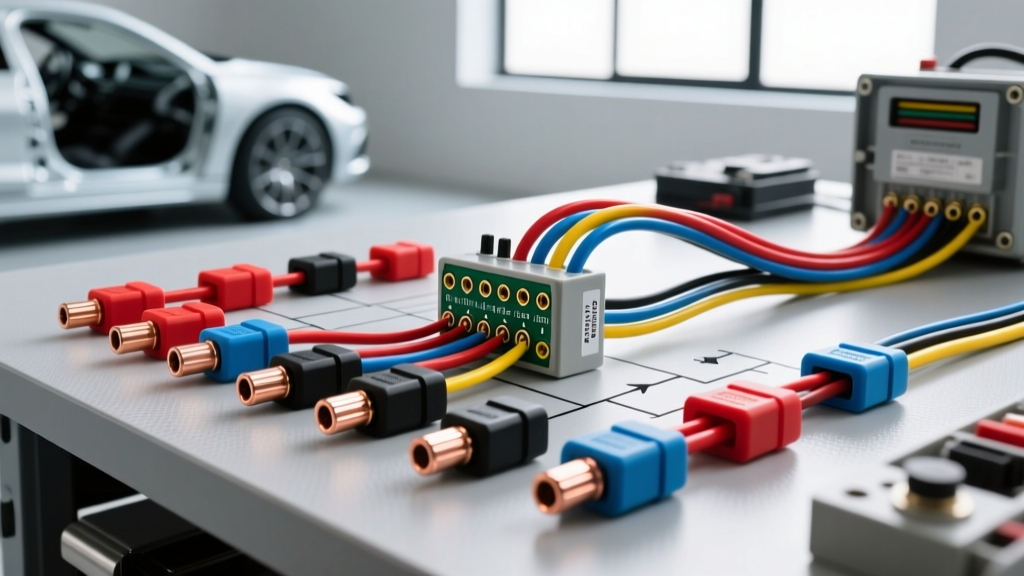
Introduction to 10 AWG Quick Connect Architecture
When designing high-amperage automotive electrical systems, 10 AWG wire is the industry standard for circuits drawing between 20 and 30 amps continuous. This gauge is heavily utilized in off-road auxiliary lighting, winch solenoid controls, dual-battery isolators, and high-power fuel pumps. However, routing a continuous 10 AWG cable from the engine bay to the chassis or bumper creates significant maintenance hurdles. This is where 10 gauge wire quick connectors become essential.
In automotive electrical engineering, the term 'quick connector' is frequently misunderstood. Novice installers often confuse 'quick splices' (vampire T-taps) with 'quick disconnects' (modular housed terminals). Using a T-tap on a 10 AWG primary power feed is a catastrophic failure point waiting to happen, as it severs copper strands and introduces massive resistance. This complete wiring diagram walkthrough will demonstrate how to properly integrate sealed, high-amperage quick disconnects into a standard Bosch-style relay schematic, ensuring modular serviceability without sacrificing conductivity or environmental sealing.
Complete Wiring Diagram Walkthrough: High-Amp Auxiliary Lighting
To understand the placement and specification of 10 gauge wire quick connectors, we must trace the current path through a standard 25-amp LED light bar circuit. This schematic utilizes TXL (Thin-wall cross-linked) 10 AWG copper wire, which features an outer diameter of approximately 0.146 inches and a continuous ampacity rating of 30A per the SAE J1128 Standard.
Phase 1: The Power Feed and Fusing
The circuit originates at the vehicle's positive battery terminal. A 10 AWG red wire is terminated with a tinned copper ring terminal and secured to the battery post. Within 18 inches of the power source, an inline MAXI fuse holder is spliced using an adhesive-lined heat-shrink butt connector. A 30A MAXI fuse is installed to protect the 10 AWG wire from thermal runaway in the event of a dead short. The red power feed then routes through the firewall grommet into the engine bay, terminating at Pin 30 of a standard 5-pin automotive relay.
Phase 2: The Relay Switching Node
The relay acts as the heavy-duty switch. Pin 86 receives a low-current trigger signal (typically 18 AWG blue wire) from a dashboard toggle switch. Pin 85 is grounded to the chassis. When the coil is energized, the internal contacts close, bridging Pin 30 (Battery Power) to Pin 87 (Load Output). The output from Pin 87 utilizes a 10 AWG yellow wire, which serves as the primary load feed to the auxiliary lights.
Phase 3: Integrating the 10 Gauge Wire Quick Connectors
Instead of routing the 10 AWG yellow wire directly to the light bar's pigtail, we introduce a modular quick disconnect exactly 24 inches from the relay. This specific placement allows the vehicle's front bumper, grille, or skid plate to be removed for service without requiring the entire wiring harness to be pulled through the firewall. The yellow wire is crimped into the male pins of a sealed quick-disconnect housing. The mating female housing is attached to the light bar's pigtail, allowing for instant, weatherproof connection and disconnection.
Quick Splices vs. Quick Disconnects: A Critical Distinction
It is vital to differentiate between the types of quick connectors available for 10 AWG wire. The following specification chart outlines why modular disconnects are mandatory for high-amp feeds, while quick splices must be strictly avoided.
| Connector Type | Function | 10 AWG Suitability | Failure Mode |
|---|---|---|---|
| Scotch-Lok / T-Tap | Pierces insulation to tap a circuit | NEVER USE | Severs copper strands; causes arcing, melting, and voltage drop. |
| Non-Insulated Butt Splice | Joins two wires permanently | Poor (Not Quick) | Requires heat shrink; not serviceable; corrodes if exposed. |
| Weather-Pack 2-Pin (50A) | Sealed modular quick disconnect | Excellent | Silicone seals degrade after 15 years; pins loosen if improperly crimped. |
| Anderson Powerpole SB50 | Genderless high-amp quick disconnect | Excellent | Unsealed; requires dielectric grease in wet environments. |
| Deutsch DT 4-Pin | Sealed multi-pin quick disconnect | Good (Requires 12 AWG pigtails) | 10 AWG wire is too thick for standard DT pins; requires stepping down. |
Precision Crimping and Pin Assembly Procedures
The reliability of any 10 gauge wire quick connector relies entirely on the mechanical crimp. Soldering is strictly prohibited in high-vibration automotive applications, as solder wicks into the wire strands, creating a rigid point that will eventually fatigue and snap under engine harmonics.
Weather-Pack 2-Pin (50A) Assembly
The Aptiv Weather-Pack series is the gold standard for sealed 10 AWG quick disconnects. The terminals feature a dual-crimp design: a core crimp for the copper strands and an insulation crimp for the wire jacket.
- Stripping: Use a precision wire stripper to remove exactly 6.5mm (1/4 inch) of TXL insulation. Do not nick the outer copper strands.
- Core Crimp: Place the terminal in the correct cavity of a ratcheting crimp tool (typically marked 10-12 AWG). The copper strands must be flush with the front of the terminal barrel.
- Insulation Crimp: The secondary barrel must fold over the wire insulation, providing strain relief.
- Seal Placement: Slide the silicone ribbed seal over the wire before crimping. Ensure the seal sits flush against the insulation crimp barrel.
- Housing Insertion: Push the crimped terminal into the nylon housing until the primary locking tang clicks. Gently tug the wire backward to verify the secondary lock has engaged.
Anderson SB50 Assembly
For applications requiring frequent high-current disconnections (such as winch power feeds or trailer auxiliaries), the Anderson Powerpole SB50 is preferred. The SB50 utilizes a rolled copper contact that accepts 10 AWG wire seamlessly. Because the housing is unsealed, it is critical to pack the connector cavity with a dielectric silicone grease to prevent galvanic corrosion and moisture ingress.
Troubleshooting and Voltage Drop Analysis
Even properly crimped 10 gauge wire quick connectors can introduce resistance if subjected to environmental contamination or terminal fretting. When troubleshooting auxiliary lighting circuits, never rely on a simple continuity test. A single strand of copper will show continuity, but will fail under a 25-amp load.
The Millivolt Drop Test
To accurately diagnose a failing quick disconnect, perform a voltage drop test under full operational load. Turn on the auxiliary lights to draw the full 25 amps. Set your digital multimeter to DC millivolts. Place the red probe on the relay-side yellow wire (upstream of the quick connect) and the black probe on the light-bar-side yellow wire (downstream of the quick connect).
- 0.00V to 0.05V: Optimal connection. Negligible resistance.
- 0.06V to 0.15V: Acceptable, but monitor for thermal buildup.
- Greater than 0.20V: High resistance detected. The quick connector terminals are likely oxidized, improperly crimped, or experiencing tang fatigue. Immediate replacement is required to prevent a thermal fire hazard.
For advanced diagnostics, utilize a thermal imaging camera after the lights have been running for 15 minutes. A healthy 10 AWG quick disconnect will remain within 5 degrees Fahrenheit of the ambient wire temperature. A localized hot spot at the connector interface visually confirms micro-arcing and terminal degradation, necessitating a complete pin and housing replacement.