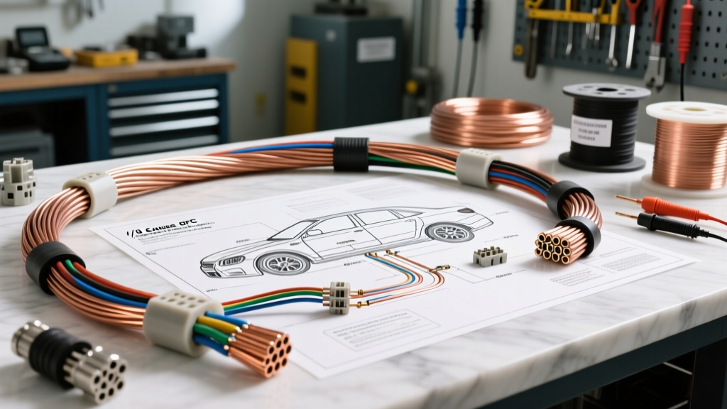
Understanding 1/0 Gauge Wire OFC in High-Amp Automotive Systems
When designing or upgrading high-current automotive, marine, or overland electrical systems, conductor selection dictates the reliability and safety of the entire platform. The 1/0 gauge wire OFC (Oxygen-Free Copper) standard represents the baseline for heavy-duty DC power transmission, commonly utilized in 200A to 350A alternator upgrades, electric vehicle (EV) battery interconnects, and heavy winch solenoid circuits. Unlike Copper Clad Aluminum (CCA), which suffers from higher resistance, galvanic corrosion at termination points, and severe strand fatigue, pure OFC ensures maximum conductivity and long-term mechanical resilience.
In this complete wiring diagram walkthrough, we will dissect a high-output dual-alternator charging system wired to a 400Ah LiFePO4 battery bank. This schematic relies entirely on 1/0 AWG OFC battery cable to minimize voltage drop and manage the immense thermal loads generated by sustained 250A charging currents. We will examine node-by-node routing, termination specifications, and the critical hardware required to maintain a fail-safe connection.
System Diagram Walkthrough: 250A Alternator to LiFePO4 Bank
The following walkthrough traces the positive and negative 1/0 OFC conductors from the high-output alternator to the battery management system (BMS). This architecture is standard in expedition vehicles, marine applications, and custom off-grid builds where voltage stability is paramount.
Node 1: Alternator B+ Output to Main ANL Fuse
The journey begins at the alternator's B+ output stud, typically an M8 (8mm) threaded terminal. Here, the 1/0 gauge wire OFC is terminated with a tinned, closed-end ring terminal. Because the engine bay environment exceeds 100°C (212°F) under load, the wire jacket must be rated for high-temperature cross-linked polyethylene (XLPE) or EPDM rubber, per SAE J1127 battery cable standards.
Within 18 inches of the alternator B+ stud, the positive 1/0 OFC conductor must pass through a 300A ANL or Class-T fuse block. This protects the main trunk line against catastrophic dead-short events. The fuse block studs are typically M10. Torque specifications for the M8 alternator nut are strictly 12-15 Nm, while the M10 fuse block nuts require 20-25 Nm. Always utilize a Belleville (conical) washer under the hex nut to maintain clamping force as the copper lug expands and contracts under thermal cycling.
Node 2: The Distribution Busbar and Mega Fuse Block
The main 1/0 OFC trunk line routes through the firewall or deck lid grommet to a centralized, tin-plated copper distribution busbar. At this node, the wire splits to feed the inverter, the DC-DC charger, and the primary battery bank. The busbar acts as a thermal mass and a low-resistance junction. Using 1/0 OFC wire with a high strand count (typically 2,100+ strands of 30 AWG tinned copper) allows the cable to bend tightly into the busbar enclosure without suffering from internal strand breakage, a common failure point with rigid, low-strand-count welding cable.
Node 3: BMS Integration and Battery Terminals
Connecting the 1/0 OFC wire to the LiFePO4 BMS requires extreme care. The BMS terminals are often M8 stainless steel studs. Stainless steel is a poor conductor compared to copper; therefore, the contact resistance between the 1/0 OFC copper lug and the BMS stud must be minimized. Apply a thin layer of Noalox or marine-grade antioxidant grease to the mating surfaces before torquing to 15 Nm. The negative 1/0 OFC return path must mirror the exact length and routing of the positive conductor to prevent electromagnetic interference (EMI) and ensure balanced voltage drop across the circuit.
1/0 AWG OFC Technical Specifications Chart
| Specification | 1/0 AWG OFC (Pure Copper) | 1/0 AWG CCA (Copper-Clad Aluminum) |
|---|---|---|
| Conductor Material | 99.95% Oxygen-Free Copper | Aluminum Core, Copper Skin |
| Cross-Sectional Area | 53.5 mm² | 53.5 mm² |
| Typical Strand Count | 2,156 (30 AWG strands) | 1,330 (Thicker strands) |
| Resistance @ 20°C (Ohms/1000ft) | 0.0983 Ω | 0.1600 Ω (approx. 60% higher) |
| Max Ampacity (SAE J1127 Engine Bay) | 285A - 320A | 190A - 220A |
| Max Ampacity (ABYC E-11 Open Air) | 375A | 240A |
| Flexibility / Fatigue Resistance | Exceptional (Fine Stranding) | Poor (Prone to Work Hardening) |
Voltage Drop and Ampacity Derating Calculations
When sizing 1/0 gauge wire OFC for a specific run, voltage drop is the primary limiting factor, not just thermal ampacity. In a 12V nominal system (charging at 14.4V), a 3% voltage drop equals 0.432V. Using the standard voltage drop formula: VD = (2 x L x I x R) / 1000 (where L is one-way length in feet, I is current in amps, and R is resistance per 1000ft).
For a 10-foot run of 1/0 OFC carrying 250A: VD = (2 x 10 x 250 x 0.0983) / 1000 = 0.49V. This results in a 3.4% drop, which is marginally above the strict 3% ideal for lithium charging. To correct this in a 250A system with a 10-foot run, the diagram must either be upgraded to 2/0 AWG or the 1/0 OFC run must be paralleled. However, for runs under 7 feet, 1/0 OFC easily maintains the sub-3% voltage drop threshold required for optimal BMS performance.
Termination, Crimping, and Torque Specifications
Terminating 1/0 gauge wire OFC requires specialized tooling. Manual indent crimpers are insufficient and dangerous for this gauge size; they create uneven compression, leaving voids inside the lug that lead to localized heating and thermal runaway. Professional automotive electricians must use a hydraulic hex-crimp tool with the correct die size (typically 50mm² or 1/0 AWG hex die).
- Stripping: Use a specialized 1/0 wire stripper to avoid scoring the outer tinned strands. Scoring creates micro-fractures that propagate under engine vibration.
- Flux and Solder (Optional but discouraged): While some diagrams call for solder-dipping 1/0 OFC, modern best practices (and ABYC E-11 standards) strictly advise against soldering battery lugs. Solder creeps under continuous mechanical load and high heat, leading to joint failure. A proper hydraulic hex crimp creates a cold-weld that is mechanically superior.
- Sealing: Slide a piece of dual-wall, adhesive-lined polyolefin heat shrink (minimum 3:1 shrink ratio) over the joint. The inner hot-melt adhesive must flow completely around the wire jacket to prevent moisture ingress and capillary-action corrosion.
Routing, Looming, and Environmental Protection
Routing 1/0 OFC through an automotive chassis requires strict adherence to clearance and abrasion protocols. The thick, heavy nature of 1/0 cable means it will sag and vibrate if not secured every 12 to 18 inches. Use UV-resistant, adhesive-backed cable mounts with stainless steel zip ties or P-clamps lined with EPDM rubber.
In the engine bay, the wire must be wrapped in Tesa 51036 PET cloth tape or enclosed in high-temperature fiberglass sleeving. Standard corrugated split-loom is unacceptable in high-heat zones as it traps heat against the wire jacket and degrades rapidly near exhaust manifolds. Maintain a minimum clearance of 6 inches from any exhaust component, and use aluminum heat-shield barriers where tight routing is unavoidable.
Common Failure Modes and Troubleshooting
Even when using premium 1/0 gauge wire OFC, systems can fail if the supporting hardware is neglected. The most common failure modes include:
- Galvanic Corrosion at the Busbar: Connecting bare copper 1/0 lugs directly to aluminum busbars without tin-plating or antioxidant compound results in rapid galvanic corrosion. This increases resistance, generating immense heat that can melt the lug insulation.
- Strand Fatigue at the Crimp Neck: If the wire is pulled tight with no service loop, engine movement and vibration will concentrate stress at the crimp neck. Over time, the fine OFC strands snap one by one, reducing the effective gauge of the wire and causing a voltage drop under load.
- Thermal Runaway from Loose Hardware: Failing to use Belleville washers on M8/M10 studs allows the connection to loosen as the copper lug undergoes thermal expansion. A loose 250A connection will arc, oxidize, and eventually weld itself into a high-resistance failure point.
Authoritative References
For complete engineering guidelines on high-current DC wiring, consult the following industry standards:
- SAE J1127: Battery Cable Standard - Governs the temperature ratings, jacket thickness, and strand requirements for automotive battery cables.
- ABYC E-11: AC & DC Electrical Systems on Boats - The gold standard for marine and overland DC wiring, detailing ampacity derating, overcurrent protection placement, and crimp specifications.