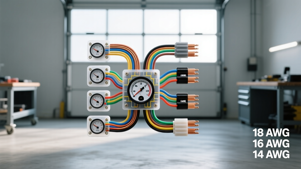
The Hidden Cost of Voltage Drop in Automotive LED Arrays
When integrating high-output illumination into off-road trucks, RV awnings, or custom car trailers, selecting the proper wire gauge for LED strip lights is rarely as simple as matching a basic wattage chart. Unlike incandescent bulbs that merely dim when starved of voltage, modern SMD (Surface Mount Device) and COB (Chip on Board) LED strips exhibit severe color shifting, flickering, and premature PCB trace failure when subjected to voltage drop. As an automotive electrical specialist, you must account for the distributed nature of the load, the forward voltage requirements of specific diode colors, and the harsh thermal environments defined by SAE J1128 standards.
Understanding LED Current Draw: SMD 5050 vs. COB Strips
Before calculating AWG (American Wire Gauge) requirements, you must establish the true amperage draw of the specific LED architecture. High-density COB strips and RGBW 5050 strips pull significantly more current per meter than standard 3528 single-color strips. Furthermore, automotive systems operate on a 12V nominal system that frequently rests at 12.6V (engine off) or spikes to 14.4V (alternator charging). Sizing your wire based on a theoretical 12.0V will result in undersized conductors when the alternator is pushing maximum current.
Real-World Power Consumption Matrix
| LED Strip Type | Density (LEDs/m) | Watts/meter | Amps/meter @ 12.6V | Max Run (End-Feed) |
|---|---|---|---|---|
| SMD 3528 (Single Color) | 60 | 4.8W | 0.38A | 10 Meters |
| SMD 5050 (RGBW) | 60 | 14.4W | 1.14A | 5 Meters |
| COB (Continuous White) | 320 | 12.0W | 0.95A | 7 Meters |
| Addressable RGB (5V) | 60 | 18.0W | 3.60A* | 3 Meters |
*Note: 5V Addressable strips require specialized DC-DC step-down converters in 12V automotive applications. The 12V input side of the converter will draw roughly 1.5A per meter, assuming 90% conversion efficiency.
The Math: Calculating Voltage Drop for Long Runs
To determine the exact wire gauge for LED strip lights in a specific vehicle routing scenario, we use the standard voltage drop formula adapted for automotive copper conductors:
VD = (2 x K x I x L) / CM
- VD: Voltage Drop
- K: Specific resistance of copper (12.9 ohms per mil foot at 75°C)
- I: Current in Amps
- L: One-way length of the wire run in feet
- CM: Circular Mils of the wire gauge (e.g., 18 AWG = 1,624 CM; 14 AWG = 4,110 CM)
For automotive LED applications, a maximum voltage drop of 3% (0.36V on a 12V system) is the target threshold. Exceeding this threshold on an RGB strip will cause the blue and green diodes to starve before the red diodes, resulting in a noticeable yellow/red color shift at the far end of the strip.
SAE J1128 Standard and Automotive Wire Types
Never use standard PVC-jacketed THHN or generic household wire in a vehicle. According to Pacer Group marine and automotive wiring guidelines, you must use cross-linked polyethylene (XLPE) insulated wire such as GXL, SXL, or TXL. GXL wire features a thinner insulation wall than standard primary wire, allowing for a tighter bend radius and more copper cross-section in confined chassis harnesses, while safely withstanding under-hood temperatures up to 125°C.
Wire Gauge for LED Strip Lights: Application Reference Chart
The following chart assumes a 12.6V nominal battery voltage, a maximum acceptable 3% voltage drop, and the use of automotive-grade GXL copper wire. Lengths represent the one-way distance from the power source/fuse block to the start of the LED strip.
| Total Current Draw | 5 ft Run | 10 ft Run | 15 ft Run | 20 ft Run |
|---|---|---|---|---|
| 2 Amps (e.g., 2m RGBW) | 18 AWG | 16 AWG | 14 AWG | 12 AWG |
| 5 Amps (e.g., 5m Single Color) | 16 AWG | 12 AWG | 10 AWG | 10 AWG |
| 10 Amps (e.g., 5m High-Density COB) | 12 AWG | 10 AWG | 8 AWG | 8 AWG |
| 15+ Amps (Dual Strips / Main Trunk) | 10 AWG | 8 AWG | 6 AWG | 6 AWG |
Advanced Wiring Topologies: Combating the 'Dark Zone'
Even if you select the perfect wire gauge for the main power run from the battery to the mounting location, the internal copper traces on the LED strip's flexible PCB will still suffer from voltage drop over long distances. To solve this, automotive upfitters utilize advanced feed topologies:
- End-Feed (Standard): Power connects to one end. Acceptable only for runs under 3 meters on high-density strips.
- Center-Feed: The main power wire (e.g., 12 AWG) reaches the physical center of the strip. The LED strip is cut in half, and solder jumpers connect the center point to both the left and right halves. This effectively halves the current traveling through the strip's internal PCB traces.
- Dual-Feed (Loop-Through): Power and ground wires are run parallel to the entire length of the strip in a thicker gauge (e.g., 14 AWG). Solder jumpers tie the parallel wire to the strip every 1.5 meters. This is mandatory for 10+ meter truck bed perimeter lighting.
Connector Selection and Terminal Crimping
Soldering wires directly to LED strip pads is prone to failure in automotive environments due to harmonic vibration and thermal expansion. Instead, utilize Aptiv (formerly Delphi) or Deutsch connector systems:
- Exterior / Under-Chassis: Use Deutsch DT Series 2-pin or 4-pin connectors with silicone rear seals and solid thermoplastic housings. Crimp terminals using a precision open-barrel crimper to ensure the wire barrel achieves a gas-tight cold weld.
- Interior / Cabin: Use Molex MX150 or JST sealed connectors. These offer a smaller form factor while maintaining positive locking mechanisms that prevent backing out during door-slam shock events.
Circuit Protection: Fusing and PWM Integration
LED strip main trunk lines must be protected within 18 inches of the power source (battery or distribution bus). Use an ATO/ATC blade fuse or Littelfuse MINI fuse rated at 125% of the continuous maximum draw. For example, a strip drawing 6A continuously requires a 7.5A or 10A fuse.
When integrating PWM (Pulse Width Modulation) dimmers or RGB controllers, place the controller after the main heavy-gauge trunk line but before the final distribution to the strips. PWM controllers generate high-frequency switching; undersized wires between the controller and the strip can act as inductors, causing electromagnetic interference (EMI) with the vehicle's CAN bus or AM radio reception. Always use twisted-pair wiring for the data lines of addressable (SPI) LED strips to reject common-mode noise.
Troubleshooting Common LED Strip Electrical Failures
| Symptom | Root Cause | Expert Fix |
|---|---|---|
| Strip turns yellow/red at the far end. | Voltage drop starving Blue/Green diodes (requires ~3.2V Vf vs Red's 2.1V). | Upgrade main feed wire by 2 AWG sizes; implement a Center-Feed topology. |
| Flickering at idle, solid while driving. | Alternator ripple voltage or poor chassis ground causing undervoltage. | Run a dedicated 12 AWG ground wire directly to the battery negative terminal; do not rely on painted chassis grounds. |
| Connector melting at the pigtail. | Using cheap friction-fit JST clones that lack proper terminal tension, causing high resistance. | Replace with genuine Molex or Deutsch terminals; verify crimp pull-out force. |
| RGB colors swapped or unresponsive. | PWM controller wired in common-anode instead of common-cathode, or vice versa. | Verify strip architecture. Most automotive strips are Common Anode (+12V constant, switched grounds). Ensure controller matches. |
By treating LED strip arrays as complex, distributed electrical loads rather than simple accessories, you ensure long-term reliability, consistent photometric output, and strict adherence to automotive fire-safety standards.