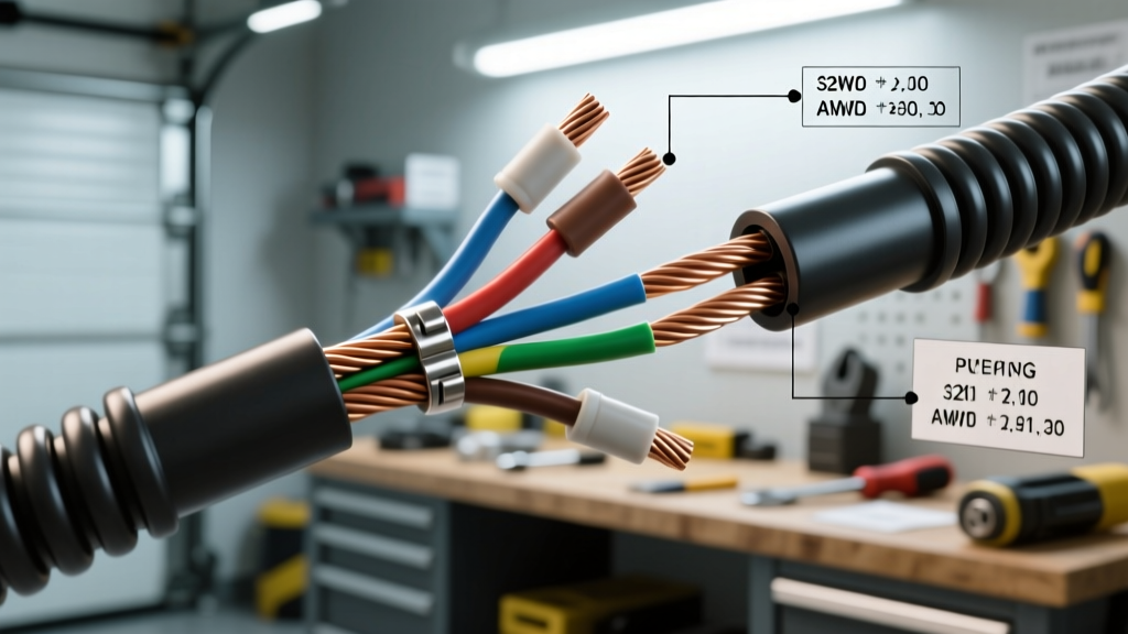
The Short Answer: Can You Splice Speaker Wire?
When upgrading automotive audio systems, a common question arises among installers and DIY enthusiasts: can you splice speaker wire? The short answer is yes, you can splice speaker wire, but the method and materials you use will dictate the longevity and acoustic performance of your system. In an automotive environment, wiring is subjected to extreme temperature fluctuations, high humidity, water intrusion (especially in door panels), and constant low-frequency vibration. A poorly executed splice will introduce resistance, cause voltage drop, and eventually lead to thermal failure or signal degradation. In this complete wiring diagram walkthrough, we will trace the audio signal path from the head unit to the transducer, analyzing where splices are necessary, how to match wire gauges, and the exact techniques required to meet mobile electronics standards.
Automotive Audio Wiring Diagram Walkthrough
To understand where and how to splice, we must first visualize the automotive audio wiring schematic. A standard aftermarket amplified system consists of three primary nodes: the Source (Head Unit/DSP), the Amplification Stage, and the Transducers (Speakers/Subwoofers). Splicing typically occurs at the transition points between these nodes.
Node 1: Head Unit to Amplifier (High-Level vs. Low-Level)
When integrating an aftermarket amplifier with a factory head unit, you must tap into the factory speaker wiring to extract a high-level signal. This is the most critical splice point in the diagram. Factory wiring is typically 20 AWG to 22 AWG. Splicing into these delicate OEM harnesses requires extreme care. Using standard crimp butt connectors here is a failure point; the thick metal barrel of the crimp will often sever the thin factory copper strands. Instead, T-taps or solder-seal splice connectors are required to maintain the structural integrity of the OEM harness while routing the signal to an amplifier's high-level inputs or a line output converter (LOC).
Node 2: Amplifier to Speaker (High-Current Runs)
The second major splice point occurs when extending or repairing speaker runs between the amplifier and the door-mounted mid-bass drivers. This usually happens at the door jamb rubber boot—the flexible conduit connecting the vehicle chassis to the door shell. Because navigating the tight bends of a door boot with thick, multi-strand oxygen-free copper (OFC) wire is difficult, installers often run a thinner gauge wire through the boot and splice it to a thicker gauge wire on either side. This introduces a bottleneck that must be carefully calculated to prevent clipping and thermal compression.
Gauge Applications: Why Wire Size Matters at the Splice Point
According to the Mobile Electronics Certification Program (MECP), maintaining consistent wire gauge throughout a high-current circuit is vital for minimizing impedance. When you splice two different wire gauges together, the smaller gauge becomes the limiting factor for current flow. This increases resistance, which in turn generates heat and reduces the damping factor of the amplifier, resulting in loose, inaccurate bass response.
| AWG Size | Max Wattage (4Ω) | Max Run Length | Recommended Application |
|---|---|---|---|
| 18 AWG | 50W RMS | 15 ft | OEM Head Unit to Door Speakers |
| 16 AWG | 100W RMS | 25 ft | Aftermarket Amp to Component Mids/Highs |
| 12 AWG | 300W RMS | 40 ft | Amplifier to Subwoofers / High-Power Mids |
| 10 AWG | 500W+ RMS | 50+ ft | Competition SPL Subwoofer Runs |
When referencing SAE J1128 standards for low-tension primary cables, it is clear that automotive wiring must handle specific thermal loads. If your amplifier outputs 75W RMS per channel, you should use 16 AWG wire. If you must splice an extension through a door boot, the extension wire must also be 16 AWG. Dropping down to 18 AWG for the door boot transition will artificially raise the impedance seen by the amplifier, potentially triggering thermal protection circuits during high-volume playback.
Step-by-Step Splicing Walkthrough (Diagram Node Analysis)
Executing a proper splice requires moving beyond basic twist-and-tape methods. Automotive electrical systems demand environmental sealing. Below is the professional workflow for splicing high-current speaker wire in a vehicle.
Step 1: Preparation and Stripping
Use a precision wire stripper calibrated for multi-strand OFC copper. Strip exactly 5/16 of an inch of insulation from both wires. Do not nick the outer strands of the copper; a nicked strand creates a microscopic stress fracture that will snap under the vibration of a car door slamming.
Step 2: The Lineman's Splice (Western Union)
Cross the exposed wires in an 'X' formation and twist them tightly around each other. This mechanical bond ensures that the wire holds itself together even before solder is applied, providing essential tensile strength against the constant vibration of the vehicle chassis.
Step 3: Soldering with Rosin-Core Flux
Apply heat using a butane or temperature-controlled soldering iron. Use 60/40 rosin-core solder specifically designed for electrical work. Never use acid-core plumbing solder, as the acid flux will eat through the copper strands over time, causing a green corrosion buildup that completely blocks audio signals. The solder should wick into the strands via capillary action, creating a solid, conductive alloy.
Step 4: Environmental Sealing
Slide marine-grade, adhesive-lined dual-wall heat shrink tubing over the splice. As you apply heat, the inner layer of hot-melt adhesive melts and flows into the wire strands, creating a waterproof seal that prevents moisture from wicking up the wire jacket into the amplifier or speaker terminals. This is mandatory for any splice located in the door panels, kick panels, or trunk areas.
Wire Color Codes and Pin Configurations
When splicing into aftermarket harnesses or verifying factory diagrams, adhering to the EIA/TIA standard color codes prevents phase cancellation. If you splice a positive lead to a negative lead, the speakers will operate out of phase, causing destructive interference and a complete loss of mid-bass frequencies.
- Front Left: White (+), White with Black Stripe (-)
- Front Right: Gray (+), Gray with Black Stripe (-)
- Rear Left: Green (+), Green with Black Stripe (-)
- Rear Right: Purple (+), Purple with Black Stripe (-)
When splicing into factory OEM wiring, colors vary wildly by manufacturer. For example, Ford often uses a solid color and a color-with-stripe combination that does not match the EIA standard, while GM may use entirely different solid colors. Always verify polarity using a 9V battery pop-test or a digital multimeter before finalizing the solder joint. According to Crutchfield's car audio wiring guides, relying on factory wire colors without testing is the leading cause of out-of-phase speaker installations.
Troubleshooting Splice Failures in the Wiring Diagram
Even with meticulous planning, splices can fail. Here is a diagnostic decision tree for troubleshooting splice-related issues in your automotive audio schematic:
Symptom: Intermittent Audio Cut-Out Over Bumps
Cause: Mechanical fatigue at the splice point. The wire was likely pulled taut through the door jamb boot without a service loop, causing the solder joint to crack under tension when the door is opened and closed.
Fix: Cut out the failed splice, leave 2 inches of slack (a service loop) inside the door cavity, and re-solder using adhesive heat shrink. Secure the wire to the door frame using Tesa tape or P-clips to absorb mechanical shock.
Symptom: High-Frequency Hiss or Alternator Whine
Cause: The splice is acting as an antenna due to poor shielding or proximity to high-current power cables. If a speaker wire splice is left exposed or runs parallel to the main 1/0 AWG power wire, it will inductively couple with the alternator's AC ripple.
Fix: Ensure all splices are fully encapsulated in heat shrink. Re-route the speaker wire so it crosses the power cable at a strict 90-degree angle, minimizing the surface area for electromagnetic interference (EMI).
Symptom: Amplifier Thermal Protection Triggering
Cause: A 'cold solder joint' at the splice point. The solder did not fully flow into the copper strands, creating a high-resistance bottleneck. As current pushes through this resistance, the splice generates excessive heat, causing the amplifier to detect an impedance anomaly and shut down.
Fix: Desolder the joint, clean the copper with isopropyl alcohol, re-twist, and apply adequate heat to ensure a shiny, smooth, and fully wicked solder joint.
Conclusion
So, can you splice speaker wire? Absolutely. However, in automotive applications, a splice is not merely a way to connect two pieces of copper; it is a critical node in your electrical schematic that must handle high current, resist environmental degradation, and survive physical vibration. By matching your AWG sizes, adhering to standard color codes, and utilizing the lineman's splice with marine-grade adhesive heat shrink, you ensure that your audio system performs flawlessly for the life of the vehicle.