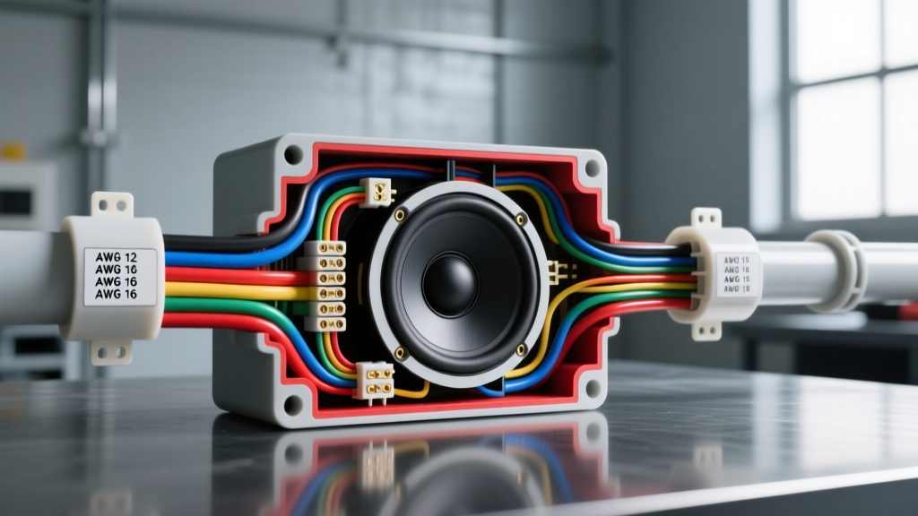
The Anatomy of a Car Audio Wiring Diagram
When upgrading a vehicle's sound system, determining the best wire gauge for speakers requires more than a simple wattage calculation. It demands a thorough understanding of signal flow, impedance, and the physical limitations of copper in a harsh automotive environment. A proper wiring diagram doesn't just show you where to connect the positive and negative terminals; it maps the transition points where wire gauge, shielding, and termination methods dictate the final audio fidelity.
In this complete wiring diagram walkthrough, we will trace the audio signal from the head unit through the digital signal processor (DSP), into the amplifiers, and finally out to the acoustic drivers. Along the way, we will apply SAE J1128 principles for low-tension automotive cabling and the Audioholics guidelines for minimizing insertion loss and preserving the amplifier's damping factor.
Standardized Wire Color Codes (CEA-2006)
Before tracing the schematic, an automotive electrical expert must adhere to the Consumer Technology Association (formerly CEA) CEA-2006 standard for aftermarket car audio wiring. Using standardized colors prevents phase cancellation and simplifies troubleshooting when tracing wires through factory kick panels and door looms.
- Left Front: White (Positive) / White with Black Stripe (Negative)
- Right Front: Gray (Positive) / Gray with Black Stripe (Negative)
- Left Rear: Green (Positive) / Green with Black Stripe (Negative)
- Right Rear: Purple (Positive) / Purple with Black Stripe (Negative)
Expert Note: When tapping into factory OEM harnesses (e.g., using a Metra or PAC integration module), factory wire colors rarely match CEA-2006. Always verify polarity with a 9V battery pop test or an oscilloscope before soldering your aftermarket speaker wire to the integration harness.
The Physics: Why Gauge Matters for Damping Factor
The primary reason we calculate the best wire gauge for speakers is to protect the system's damping factor. Damping factor is the amplifier's ability to control the mechanical movement of the speaker cone, particularly the voice coil, after the audio signal stops.
The formula is: Damping Factor = Speaker Impedance / (Amp Output Impedance + Wire Resistance).
If you use 18 AWG wire for a 300-watt subwoofer, the thin wire introduces significant resistance. This resistance acts as a buffer, effectively ruining the amplifier's grip on the subwoofer cone. The result is "muddy" or "boomy" bass, regardless of how expensive your amplifier is. According to Crutchfield's car audio wiring guidelines, keeping total wire resistance below 5% of the speaker's nominal impedance is the golden rule for high-fidelity audio.
AWG Specification Chart: RMS Wattage vs. Run Length
| AWG Size | Strand Count (OFC) | Max RMS Wattage (4-Ohm) | Max Run Length (One Way) | Best Application |
|---|---|---|---|---|
| 18 AWG | 16-Strand | 50W | 12 Feet | Tweeters, High-Pass Crossovers |
| 16 AWG | 26-Strand | 100W | 20 Feet | Standard 6.5" Door Midbass / Coaxials |
| 14 AWG | 41-Strand | 150W | 25 Feet | High-Power Component Midranges |
| 12 AWG | 65-Strand | 300W | 20 Feet | 8" Midbass, Shallow-Mount Subwoofers |
| 10 AWG | 105-Strand | 500W+ | 30 Feet | Dedicated Subwoofer Enclosures |
Diagram Walkthrough: Tracing the Speaker Circuit
Let's walk through a comprehensive 3-way active car audio schematic, identifying the exact wire gauge and termination requirements at every node.
Stage 1: Head Unit to DSP / Amplifier (Signal Level)
The walkthrough begins at the head unit. If you are running a high-level signal to a DSP with summing capabilities, you will use 18 AWG twisted-pair speaker wire. Twisting the positive and negative wires together (one twist per inch) rejects electromagnetic interference (EMI) generated by the vehicle's alternator and CAN bus networks. If running RCA (low-level), you bypass speaker wire here entirely, using shielded coaxial RCA cables.
Stage 2: Amplifier Output to Passive Crossover
If your system utilizes passive crossovers, the wire leaving the amplifier's binding posts must handle the full, unfiltered RMS wattage of the component set. For a typical 100W RMS component set, 16 AWG OFC (Oxygen-Free Copper) is mandatory.
- Termination: Use closed-end spade terminals crimped with a ratcheting crimper, then sealed with 3M dual-wall adhesive heat shrink. Never leave bare copper exposed inside an amplifier rack, as automotive humidity will cause rapid oxidation.
Stage 3: Crossover to Tweeter and Midrange (The Critical Zone)
Inside the door panel or A-pillar, space is at a premium. The passive crossover splits the frequencies.
- To the Tweeter: Because high frequencies carry very little current, and tweeters present a high impedance (often 4 to 8 ohms), 18 AWG wire is perfectly acceptable here. It is flexible and easy to route through tight A-pillar clips.
- To the Midrange: The midrange driver handles the critical vocal frequencies. Stick to 16 AWG to maintain a high damping factor, ensuring tight, punchy mid-bass response.
Stage 4: Amplifier to Subwoofer (High Current Demand)
The final leg of our diagram is the subwoofer run. Subwoofers demand massive instantaneous current to move heavy cones. Running 16 AWG wire to a 500W subwoofer will result in severe voltage sag and thermal compression.
- Gauge Selection: Use 12 AWG or 10 AWG OFC wire.
- Routing: Never run high-current speaker wire parallel to the vehicle's main ECU wiring harness. Keep at least a 6-inch separation to prevent inductive coupling, which manifests as a high-pitched whine that changes with engine RPM.
- Termination at the Sub: Use heavy-duty 10 AWG ring terminals bolted directly to the subwoofer's binding posts. If the sub uses push-terminals, solder the 10 AWG wire directly to a high-tension spade to prevent the wire from vibrating loose under heavy excursion.
Material Science: OFC vs. CCA
When sourcing the best wire gauge for speakers, the material is just as critical as the thickness. Copper-Clad Aluminum (CCA) wire is cheaper and lighter, but aluminum has only 61% of the conductivity of pure copper. Furthermore, CCA wire is highly susceptible to galvanic corrosion when exposed to the moisture trapped inside car doors. Once the copper cladding chips or oxidizes, the underlying aluminum rapidly degrades, turning into a high-resistance resistor that destroys audio quality. Always specify ASTM B172 compliant Oxygen-Free Copper (OFC) for any permanent automotive audio installation.
Troubleshooting Matrix: Gauge & Connection Failures
Even with a perfect diagram walkthrough, real-world installations encounter faults. Use this decision tree to diagnose speaker wire issues:
| Symptom | Probable Cause | Diagnostic Fix |
|---|---|---|
| Bass sounds weak or "disconnects" at high volume. | Wire gauge too thin (e.g., 16 AWG on a 400W sub); thermal resistance spike. | Upgrade to 10 AWG OFC; verify amplifier terminals are torqued to 1.5 Nm. |
| Vocals sound hollow; imaging is dead center instead of dash-wide. | Out-of-phase wiring (Polarity reversal) at one of the door speakers. | Check CEA-2006 stripe orientation. Use a phase tester or 9V battery pop test. |
| Intermittent popping or crackling when hitting bumps. | Poor termination; stranded wire fraying inside a cheap crimp connector. | Cut back to fresh copper. Solder and seal with marine-grade adhesive heat shrink. |
| High-pitched alternator whine in tweeters only. | Speaker wire routed too close to factory ECU/CAN bus lines. | Reroute A-pillar speaker wire away from the dash harness; use twisted pair. |
Final Installation Verification
After completing the physical wiring according to this walkthrough, perform a multimeter continuity test before powering on the amplifiers. Set your multimeter to the Ohms (Ω) setting. Disconnect the speaker wire from the amplifier side and measure across the positive and negative terminals at the speaker end. A standard 4-ohm car speaker should read between 3.2 and 3.8 ohms. If you read 0.1 ohms, you have a dead short (pinched wire in the door jamb boot). If you read infinite resistance (OL), you have an open circuit (broken strand or failed solder joint). Only once the impedance matches the driver's specification should you reconnect the amplifier and tune the DSP.