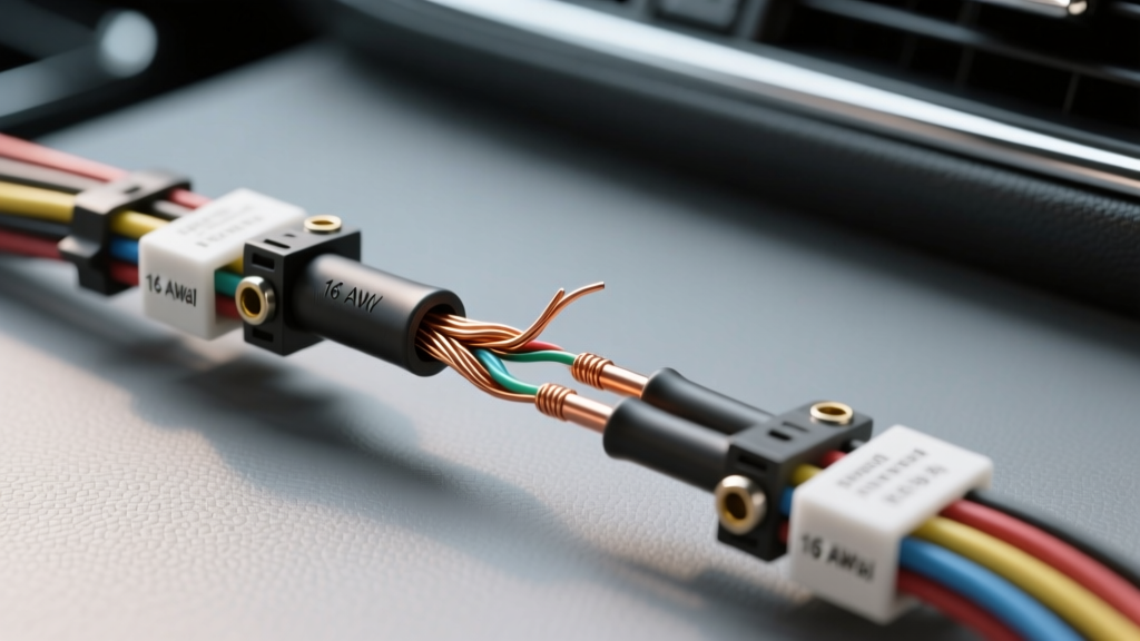
Why Proper Splicing Matters in Automotive Audio
Upgrading a factory car audio system almost always requires extending, tapping, or replacing existing speaker wiring. However, the automotive environment is exceptionally hostile to electrical connections. Unlike home theater setups, vehicle wiring must endure extreme temperature fluctuations, constant vibration, high humidity, and exposure to road salts. Finding the best way to splice speaker wire is not just about maintaining a clean aesthetic; it is about preserving signal integrity, preventing impedance mismatches, and avoiding catastrophic short circuits that can destroy expensive aftermarket amplifiers.
When dealing with low-level audio signals and high-current speaker outputs, a poor splice introduces electrical resistance. This resistance dampens the damping factor of your amplifier, resulting in muddy bass response and thermal compression. Furthermore, according to the IPC/WHMA-A-620 standard for cable assemblies, mechanical connections in high-vibration environments must be reinforced to prevent fatigue failure. In this guide, we break down the exact materials, gauges, and techniques required to execute flawless speaker wire splices in your vehicle.
Understanding Speaker Wire Gauges and Materials
Before making any cuts, you must verify the American Wire Gauge (AWG) and the conductor material of both the OEM and aftermarket wires. Most factory head units utilize 18 AWG wire, which is sufficient for low-power (15W-25W RMS) internal amplifiers. However, when adding external amplifiers or high-efficiency component speakers, upgrading to 16 AWG or 14 AWG Oxygen-Free Copper (OFC) is mandatory.
Avoid Copper-Clad Aluminum (CCA) wire at all costs. CCA is significantly more brittle than OFC and possesses a higher resistance per foot. More importantly, splicing CCA to OEM OFC wiring creates a galvanic corrosion cell in the presence of moisture, rapidly degrading the connection from the inside out.
Automotive Speaker Wire Gauge Specifications
| AWG Size | Max Current (Chassis) | Resistance per 10 ft | Best Application |
|---|---|---|---|
| 18 AWG | 16 Amps | 0.064 Ohms | OEM head unit replacements, low-power tweeters |
| 16 AWG | 22 Amps | 0.040 Ohms | Standard 6.5-inch coaxials, mid-range door speakers |
| 14 AWG | 32 Amps | 0.025 Ohms | High-power component systems, mid-bass drivers, subwoofers |
CEA-2006 Standard Color Codes
To ensure correct phase and polarity when splicing into factory harnesses, adhere to the CEA-2006 Mobile Electronics Cabling Standard. Reversing polarity on even a single speaker will cause acoustic phase cancellation, severely degrading your soundstage.
| Speaker Location | Positive (+) Wire | Negative (-) Wire |
|---|---|---|
| Left Front | White | White with Black Stripe |
| Right Front | Gray | Gray with Black Stripe |
| Left Rear | Green | Green with Black Stripe |
| Right Rear | Purple | Purple with Black Stripe |
Comparing the Top 3 Splicing Methods
Automotive technicians and car audio competitors generally rely on three primary splicing methods. Here is how they stack up against the rigors of the automotive environment.
| Method | Vibration Resistance | Moisture Resistance | Verdict |
|---|---|---|---|
| Twist & Electrical Tape | Poor | Poor | Never use. Adhesive melts in summer heat, exposing copper to corrosion. |
| Crimp Caps / Butt Connectors | Good | Fair | Acceptable for interior, dry locations. Prone to oxidation over time. |
| Marine-Grade Solder Seal | Excellent | Excellent | The absolute best way to splice speaker wire. Waterproof and strain-relieved. |
Step-by-Step: The Best Way to Splice Speaker Wire
For a permanent, waterproof, and vibration-proof connection, marine-grade adhesive-lined solder seal wire connectors are the undisputed champion. These connectors feature a polyolefin heat-shrink tube lined with a thermoplastic adhesive and a central ring of flux-cored solder.
Required Tools
- Marine-grade solder seal connectors (sized for 16-14 AWG or 22-18 AWG)
- Precision wire strippers (to avoid nicking OFC strands)
- Heat gun with a reflector nozzle (do not use an open flame lighter)
- Flush cutters
Execution Steps
- Strip the Insulation: Strip exactly 5/16 inch (8mm) of insulation from both wire ends. Ensure no copper strands are nicked or cut, as this creates a weak point for fatigue failure.
- Prep the Connector: Slide the solder seal connector over one of the wires before twisting them together. This is the most commonly forgotten step.
- Twist the Conductors: Twist the exposed OFC strands together in a tight, clockwise helix. The mechanical twist should be strong enough to hold the wires together before the solder melts.
- Position the Connector: Slide the connector over the twisted joint, ensuring the central solder ring is perfectly centered over the bare copper.
- Apply Heat: Using a heat gun set to approximately 250°C (480°F), apply heat to the center of the connector first. Watch for the solder ring to melt and flow into the copper strands.
- Seal the Ends: Once the solder flows, move the heat gun outward toward the ends of the connector. This forces the internal adhesive to melt and squeeze out the ends, creating a 100% waterproof environmental seal.
Navigating the Door Boot: Moisture and Flex Fatigue
The most critical area in automotive speaker wiring is the door boot—the rubber accordion tube connecting the vehicle's A-pillar or B-pillar to the door hinge. Wires routed through this boot undergo tens of thousands of flex cycles and are exposed to heavy moisture ingress.
According to SAE J1128 guidelines for automotive cable durability, wiring in high-flex zones must utilize high-strand-count wire. Standard 16 AWG wire might have 26 strands, but high-flex silicone speaker wire utilizes up to 104 micro-strands. When splicing inside or near the door boot, you must use the solder-seal method described above, followed by wrapping the splice in Tesa cloth harness tape. This prevents the rigid ends of the heat shrink from chafing against adjacent wires inside the tight rubber boot, which can eventually wear through the insulation and cause a short to the door chassis.
Troubleshooting Common Splice Failures
Even with the best intentions, splices can fail if the underlying physics are ignored. Use this decision tree to diagnose post-installation audio issues.
Symptom: Audio Cuts Out When Opening/Closing the Door
- Cause: Wire fatigue or a broken splice inside the door boot. The rigid ends of a poorly heated shrink tube acted as a fulcrum, snapping the copper strands during flex cycles.
- Fix: Cut out the damaged section. Re-splice using high-strand-count OFC wire and ensure the heat shrink transitions smoothly without hard edges.
Symptom: Muddy Bass and Low Volume at High Power
- Cause: Thermal compression due to high-resistance splices. If CCA wire was used, or if the solder ring failed to fully melt and penetrate the copper strands, the splice acts as a resistor, robbing the speaker of damping factor.
- Fix:Replace all CCA wiring with pure OFC. Re-do all splices, ensuring the heat gun reaches the necessary temperature to fully liquefy the flux-cored solder.
Symptom: Intermittent Popping or Crackling
- Cause: Micro-arcing inside a crimp cap or a twisted-and-taped connection that has oxidized and loosened due to thermal expansion and contraction in the door panel.
- Fix: Strip back the oxidized copper until bright, shiny metal is visible. Execute a fresh marine-grade solder seal splice and secure the wire to the door frame using a plastic push-clip to relieve mechanical strain on the joint.
By prioritizing OFC materials, adhering to CEA-2006 color standards, and utilizing adhesive-lined solder seals, you ensure your car audio system delivers pristine, uninterrupted sound for the life of the vehicle.