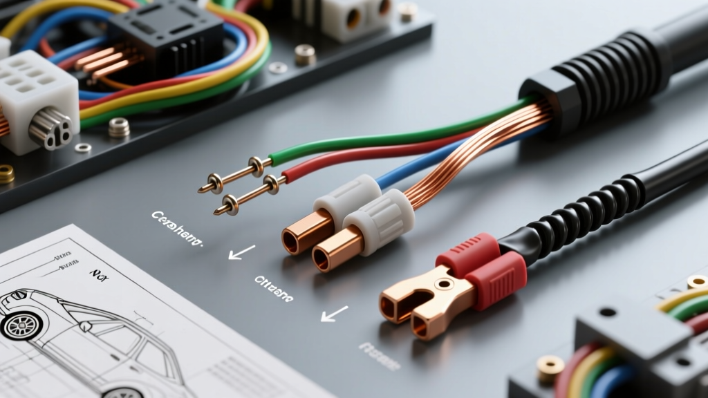
The Definitive Guide on How to Splice Speaker Wires in Automotive Environments
When upgrading a car audio system, running new wire to your door panels, kick panels, or rear deck is inevitable. However, the transition points between your amplifier, head unit harness, and speaker voice coils are critical vulnerability zones. Learning how to splice speaker wires correctly is not just about establishing electrical continuity; it is about preserving signal integrity, maintaining consistent impedance, and ensuring the connection survives the hostile environment of a vehicle interior.
Unlike home audio, automotive wiring must endure extreme temperature fluctuations, high humidity inside door cavities, and constant low-frequency vibration from the chassis and road noise. A poor splice can lead to thermal compression loss, galvanic corrosion, and intermittent shorts that can trigger an amplifier's protection mode or permanently damage an output channel. This product comparison and selection guide evaluates the most common splicing methods, connectors, and techniques to help you choose the right solution for your specific wire gauge application.
Understanding Speaker Wire Gauges and Automotive Color Codes
Before selecting a splicing product, you must identify your wire gauge and composition. Standard car audio applications typically utilize Oxygen-Free Copper (OFC) or Copper-Clad Aluminum (CCA) stranded wire in the following sizes:
- 18 AWG: Standard for head unit outputs (15W–50W RMS) and short runs under 12 feet.
- 16 AWG: Recommended for aftermarket component speakers, mid-bass drivers, and runs exceeding 12 feet.
- 12 AWG: Reserved for high-level subwoofer inputs or high-power active midrange drivers (100W+ RMS).
When splicing into a factory harness or extending an aftermarket harness, adhering to the Consumer Technology Association (CTA) standard color codes prevents phase cancellation and channel miswiring:
- Left Front: White (+) / White with Black Stripe (-)
- Right Front: Gray (+) / Gray with Black Stripe (-)
- Left Rear: Green (+) / Green with Black Stripe (-)
- Right Rear: Purple (+) / Purple with Black Stripe (-)
Product Comparison: Splicing Methods & Connectors
There is no single "best" connector for every scenario. The right choice depends on your skill level, the tools available, and the specific location of the splice (e.g., inside a dry cabin vs. inside a wet door cavity).
1. Adhesive-Lined Heat Shrink Butt Splices (The Gold Standard)
Dual-wall polyolefin heat shrink butt connectors feature an inner layer of thermoplastic adhesive. When heated, the outer tubing shrinks (typically at 120°C) while the inner adhesive melts (around 80°C), flowing into the wire strands and creating a watertight, vibration-proof seal.
- Best For: Door panel speaker runs, subwoofer enclosures, and any splice exposed to moisture.
- Pros: Superior strain relief, completely waterproof, prevents oxidation.
- Cons: Requires a quality ratcheting crimp tool and a dual-temperature heat gun. Bulky profile can make routing through tight rubber door boots difficult.
2. Solder and Heat Shrink Tubing
Soldering involves melting a 60/40 rosin-core alloy over the twisted copper strands, followed by sealing with standard heat shrink. While solder provides excellent electrical conductivity, it has a major drawback in automotive applications: it creates a rigid point on a flexible stranded wire.
- Best For: Static connections inside sealed amplifier distribution blocks or interior cabin splices where flexing is minimal.
- Pros: Lowest possible electrical resistance; excellent for joining dissimilar metals (like OFC to CCA) if done correctly with dielectric grease.
- Cons: High skill floor. The rigid solder joint can fatigue and snap under the constant vibration of a door panel or hatchback. IPC/WHMA-A-620 standards warn against solder joints in high-flex environments.
3. Step-Down Crimp Caps (Ultrasonic / Closed-End Connectors)
Often used in OEM factory repairs, these copper or brass caps are crimped over multiple stripped wires using a specialized ultrasonic welder or a heavy-duty indent crimper. They are then covered with electrical tape or liquid electrical tape.
- Best For: Quick factory harness repairs in dry areas under the dash.
- Pros: Very low profile, fast to install in production environments.
- Cons: Poor moisture resistance unless heavily coated in silicone. Difficult to inspect for proper strand capture.
4. Twist-On Wire Connectors (Wire Nuts)
Verdict: Never use in a vehicle. Wire nuts rely on tension and gravity to stay seated. The constant vibration of a vehicle chassis will inevitably back the nut off the wires, leading to arcing, short circuits, and blown amplifier channels. Furthermore, they offer zero moisture protection.
Technical Selection Matrix
| Splicing Method | Vibration Resistance | Moisture Seal | Tool Required | Recommended AWG | Application Zone |
|---|---|---|---|---|---|
| Adhesive Heat Shrink Butt | Excellent (SAE J1128 compliant) | Waterproof (IP67) | Ratcheting Crimper, Heat Gun | 18-16 AWG (Red), 16-14 AWG (Blue) | Doors, Hatchbacks, Engine Bay |
| Solder + Heat Shrink | Poor (Fatigue Risk) | Water-Resistant | Soldering Iron, Heat Gun | 16-12 AWG | Static Cabin, Amp Racks |
| Step-Down Crimp Caps | Good | Poor (Requires Silicone) | Indent Crimper | 22-18 AWG | Under Dash, Dry Harness |
| Twist-On Caps (Nuts) | Fail (Vibration Back-off) | None | Pliers / Hands | N/A | NEVER USE IN AUTOMOTIVE |
Step-by-Step: How to Splice Speaker Wires Using Adhesive Butt Connectors
For 95% of aftermarket car audio installations, adhesive-lined heat shrink butt splices are the definitive choice. Follow this procedure to ensure a permanent, low-resistance connection.
- Select the Correct Connector Size: Use Red connectors for 22-18 AWG wire, and Blue connectors for 16-14 AWG wire. Using a Blue connector on an 18 AWG wire will result in a loose crimp that pulls out under tension.
- Strip the Wire Precision: Use an automatic wire stripper (like the Klein Tools 11055) set to the exact gauge. Strip exactly 5/16" (8mm) of insulation. Do not nick the copper strands, as this creates a weak point for fatigue.
- Insert and Align: Insert the stripped ends of both wires into the metal barrel of the butt connector. Ensure the wires meet in the exact center of the barrel. You should see a tiny gap of copper in the middle if using a clear shrink tube, but standard opaque tubes require tactile verification.
- Execute a Ratcheting Crimp: Use a ratcheting crimper with oval or indent dies. Place the metal barrel in the die and squeeze until the ratchet releases. This ensures the exact amount of pressure is applied to cold-weld the copper strands to the brass barrel without crushing the wire.
- Apply Heat: Using a dual-temperature heat gun set to roughly 250°C (480°F), apply heat evenly starting from the center of the connector and moving outward toward the wire insulation. Stop heating the moment the adhesive bubbles slightly out of the ends of the connector. This indicates the inner thermoplastic has fully encapsulated the copper strands.
Troubleshooting Common Splice Failures
Even experienced installers encounter issues when pushing high-current AC audio signals through custom wiring. Here is a diagnostic tree for common splice-related failures:
Symptom: Amplifier goes into "Protect" mode when bass hits.
- Cause: The splice has high resistance or is shorting to the chassis during door flex.
- Fix: Inspect the heat shrink. If it is not fully sealed, moisture has entered, causing copper oxide (a semiconductor) to form. Cut out the splice, clean the wire with isopropyl alcohol, and re-crimp using a fresh adhesive-lined connector. Ensure the wire is secured with Tesa tape away from the window regulator tracks.
Symptom: Vocal imaging is dead-center or "hollow" sounding.
- Cause: Out-of-phase wiring caused by misidentifying the CTA color codes at the splice point (e.g., splicing a White/Black negative to a solid White positive).
- Fix: Use a digital multimeter or an AA battery pop-test to verify polarity at the speaker terminal before sealing the splice. A 9V battery touched to the wire should push the speaker cone outward on the positive (+) terminal.
Symptom: High-frequency roll-off or muffled sound.
- Cause: Galvanic corrosion occurring at a splice where CCA (Copper-Clad Aluminum) wire was spliced directly to OFC (Oxygen-Free Copper) wire without dielectric protection.
- Fix: When transitioning between CCA and OFC, the aluminum core of the CCA wire will rapidly oxidize when exposed to bare copper and moisture. Always use adhesive-lined heat shrink to completely starve the joint of oxygen, or apply a dab of dielectric grease inside the barrel before crimping.
Final Thoughts on Automotive Audio Integrity
Mastering how to splice speaker wires is a foundational skill that separates amateur installs from professional, competition-grade builds. By abandoning electrical tape and solder in high-flex zones, and instead relying on SAE-compliant adhesive heat shrink butt connectors, you guarantee that your audio system will deliver pristine, uncolored sound for the lifespan of the vehicle. Always invest in high-quality OFC wire, precision ratcheting crimpers, and marine-grade heat shrink to ensure your car audio system performs flawlessly in any environment.