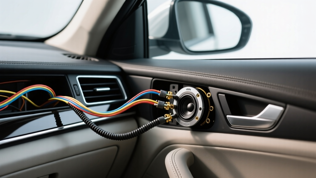
The Role of 20 Gauge Speaker Wire in Automotive Audio
When upgrading car audio systems, enthusiasts often default to 16 AWG or 14 AWG oxygen-free copper (OFC) wire for door speakers and subwoofers. However, 20 gauge speaker wire serves a highly specialized, critical role in modern vehicle audio installations. Measuring just 0.0320 inches (0.812 mm) in diameter, 20 AWG is the optimal choice for routing high-frequency signals to OEM tweeters, A-pillar pods, dash-mounted fill speakers, and motorcycle fairing audio systems where conduit space and weight are severely restricted.
Using 20 AWG wire for 6.5-inch mid-bass drivers will result in unacceptable voltage drop and high-frequency roll-off due to the wire's inherent resistance. But for tweeters—which typically draw less than 15 watts RMS and reproduce frequencies above 2,500 Hz—20 AWG provides a perfect balance of flexibility, concealability, and electrical efficiency. This practical how-to guide details the exact specifications, routing techniques, and termination methods required to install 20 gauge speaker wire safely and effectively in automotive environments.
Technical Specifications and Limitations
Before pulling wire through your vehicle's chassis, it is vital to understand the electrical characteristics of 20 AWG stranded copper. The SAE International J1128 standard outlines the baseline requirements for low-tension primary cables, which informs how we treat thin-gauge wiring in harsh automotive environments.
| Specification | 20 AWG OFC (Oxygen-Free Copper) | 20 AWG CCA (Copper-Clad Aluminum) |
|---|---|---|
| Wire Diameter | 0.0320 in (0.812 mm) | 0.0320 in (0.812 mm) |
| Resistance per 1,000 ft | 10.15 Ohms | ~15.2 Ohms |
| Max Recommended Power (4-Ohm) | 50W RMS (Runs under 10 ft) | 25W RMS (Runs under 5 ft) |
| Strand Count (Typical) | 7 to 10 strands of 30 AWG | 7 to 10 strands of 30 AWG |
| Insulation Type | PVC or TPE (High-Temp) | PVC (Standard) |
The Danger of CCA in Thin Gauges
Never use Copper-Clad Aluminum (CCA) for 20 gauge speaker wire applications. Because 20 AWG already has a relatively high DC resistance (10.15 Ohms per 1,000 feet), introducing an aluminum core increases that resistance by nearly 50%. This acts as an unintended passive crossover, attenuating high frequencies and drastically reducing the damping factor of your amplifier. Always verify that your spool is stamped with OFC or pure copper certifications.
Tools and Materials Required
- Wire Strippers: Precision micro-strippers with a dedicated 20-22 AWG notch. Standard automotive strippers will sever the fragile 30 AWG sub-strands.
- Micro-Crimpers: Ratcheting crimpers designed for 0.64mm and 1.2mm Molex or Metri-Pack terminals.
- Soldering Iron & Solder: 63/37 Rosin-core eutectic solder (melts at a lower temperature, preventing insulation melt-back on thin wires).
- Adhesive-Lined Heat Shrink: 3/32-inch dual-wall marine-grade heat shrink with internal sealant.
- Tesa Tape: Fleece wiring harness tape for OEM-style rattles-free bundling.
- Multimeter & Phase Tester: For verifying continuity and acoustic polarity.
Step-by-Step Installation Guide
Step 1: OEM Harness Integration and Pin Extraction
Modern vehicles rarely offer bare wire taps for tweeters; they use micro-connectors. For example, General Motors frequently utilizes a 4-pin Metri-Pack 150 connector for dash-mounted tweeters, while Ford often employs a 2-pin Molex MX150 harness. 20 gauge speaker wire is the exact correct size for the 0.64mm terminal crimp profile of these micro-connectors.
- Disconnect the negative battery terminal to prevent shorting the head unit's internal amplifier IC.
- Use a specialized pin extraction tool to depress the locking tang on the OEM connector.
- Strip exactly 3mm of insulation from the 20 AWG wire. Do not twist the strands; keep them parallel.
- Insert the wire into the micro-terminal and use a ratcheting micro-crimper. A proper crimp will pass a 3-lb pull test without the wire slipping.
- Slide the terminal back into the connector housing until you hear a definitive 'click'.
Step 2: Routing Through the A-Pillar and Dash
Routing 20 gauge speaker wire requires meticulous attention to vehicle safety systems. The A-pillar houses the side-curtain SRS airbag, which is identifiable by its bright yellow wiring loom.
- Never zip-tie or tape speaker wire to the yellow SRS harness. In the event of deployment, the airbag can tear the speaker wire, causing a short circuit or altering the airbag's deployment trajectory.
- Route the 20 AWG wire along the factory body harness, securing it with Tesa fleece tape every 6 inches. This prevents the thin wire from vibrating against the sheet metal and creating acoustic rattles.
- When passing through the firewall or dash support beam, use a rubber grommet and apply dielectric grease to the wire to prevent moisture wicking into the cabin.
Step 3: Termination and Soldering at the Tweeter
Tweeter terminals are exceptionally small, and the mechanical stress on 20 AWG wire can cause the thin strands to fatigue and snap over time due to door slams and vehicle vibration. Soldering is mandatory for long-term reliability.
- Strip 5mm of insulation from the 20 AWG wire.
- 'Tin' the exposed copper by applying a small amount of 63/37 rosin-core solder to the wire strands.
- Wrap the tinned wire around the tweeter's spade terminal or feed it through the terminal eyelet.
- Apply the soldering iron to the terminal, not the wire. Allow the heat to transfer to the wire for 2 seconds, then feed solder into the joint until it flows smoothly.
- Slide a piece of 3/32-inch adhesive-lined heat shrink over the joint and apply heat. The internal adhesive will melt and seal out humidity, preventing copper oxidation.
Step 4: Polarity and Phase Verification
Tweeters are highly directional and phase-sensitive. If the 20 AWG wire is wired out of phase (Positive to Negative), the acoustic output from the tweeter will cancel out the midrange frequencies at the crossover point, resulting in a hollow, 'nasal' soundstage. According to the Mobile Electronics Certification Program (MECP) guidelines, verifying phase is a mandatory final step.
- Use a dedicated audio phase meter, placing the microphone directly against the tweeter dome.
- Alternatively, perform a 'pop test' using a 9V battery. Momentarily touch the positive wire to the positive battery terminal and the negative to the negative. If the tweeter dome pushes outward, your polarity is correct.
Troubleshooting Common 20 AWG Failures
| Symptom | Probable Cause | Expert Fix |
|---|---|---|
| High-frequency roll-off or muffled tweeters | Excessive voltage drop due to run length exceeding 15 feet, or use of CCA wire. | Replace with OFC wire or upgrade to 18 AWG for runs over 15 feet. Verify amplifier crossover settings. |
| Intermittent audio cutting out over bumps | Tinsel lead fatigue or micro-fractures in the 20 AWG strands from improper stripping. | Inspect the wire near the termination point. Re-strip using precision 22 AWG notches and re-solder. |
| Alternator whine in the tweeters | 20 AWG wire routed too close to high-current 12V power cables or ignition coils. | Reroute the speaker wire on the opposite side of the chassis. Twist the positive and negative 20 AWG wires together (2 twists per inch) to reject EMI. |
| Corrosion at the tweeter terminal | Moisture ingress due to lack of environmental sealing. | Cut back the corroded wire, re-terminate, and seal with dual-wall adhesive heat shrink. |
Final Thoughts on Wire Management
While 20 gauge speaker wire is not suited for high-power subwoofers or mid-bass drivers, it remains an indispensable tool in the mobile electronics installer's arsenal. Its thin profile allows for stealthy integration into tight OEM dash pods, motorcycle handlebars, and sail panels without compromising the structural integrity of the vehicle's trim. By adhering to strict stripping tolerances, utilizing eutectic solder, and respecting SRS airbag routing protocols, you can achieve a factory-fit, high-fidelity audio upgrade that withstands the harsh thermal and vibrational realities of the automotive environment.
For further reading on automotive electrical standards and installation best practices, refer to the Crutchfield Speaker Installation Guide and your vehicle's specific OEM service manual for exact connector pinouts and torque specifications.