Introduction to 12V System Voltage Drop and Wire Sizing
When an aftermarket fuel pump starves at high RPM, an LED light bar flickers, or a winch solenoid chatters, the culprit is rarely the component itself. It is almost always inadequate wire sizing or poor termination. Selecting the correct wire gauge for 12V applications requires a strict understanding of voltage drop, continuous current draw, and thermal derating. Many DIYers rely on generic household AC wiring charts, which fail catastrophically in 12V DC automotive environments where amperage is high and system voltage is low. According to the SAE J1128 Low Tension Cable Standard, automotive wiring must account for under-hood temperature extremes and specific copper stranding configurations. This guide provides a step-by-step diagnostic flow to identify, measure, and rectify 12V circuit failures caused by improper wire gauge selection.
Step 1: Measure the Baseline Voltage Drop Under Load
The first rule of automotive electrical troubleshooting is to never measure voltage statically. A multimeter will read 12.6V on an undersized wire if there is no current flowing through it. Voltage drop only reveals itself when the circuit is under load.
- Static Test: Connect your Digital Multimeter (DMM) directly to the battery terminals. With the engine running, you should see between 13.8V and 14.4V. Record this as your baseline.
- Load Test: Move the red probe to the 12V+ feed pin at the accessory connector (e.g., the power pin on a Deutsch DT plug or Metri-Pack 280 connector) and the black probe to a known good chassis ground. Activate the accessory.
- Calculate the Drop: Subtract the load voltage from the baseline battery voltage. If the battery reads 14.2V and the accessory reads 12.1V, you have a 2.1V drop. This represents a 14.7% voltage drop, which is catastrophic for sensitive ECUs, fuel pumps, and high-draw lighting.
SAE guidelines and Painless Performance Wiring Guidelines recommend a maximum 3% voltage drop (0.36V on a 12V system) for critical engine management and fuel delivery circuits, and a maximum 5% drop (0.60V) for non-critical accessories like interior lighting.
Step 2: Identify the Symptom and Calculate True Current Draw
Before upsizing your wire, you must calculate the true continuous current draw of the failing component. Marketing wattage is notoriously misleading. For example, a '500W' car audio amplifier does not draw 41A continuously; its draw depends on RMS output and Class D efficiency. Conversely, inductive loads like fuel pumps and cooling fans experience massive inrush currents and varying operational draws based on system pressure or mechanical resistance.
Consider the Walbro 255 LPH fuel pump (Part # F90000192). At 40 PSI, it draws roughly 12 Amps. However, at 80 PSI (common in boosted applications with rising-rate fuel pressure regulators), current draw spikes to 18 Amps or more. If this pump is wired with 16 AWG wire over a 12-foot run from the front-mounted battery, the resistance will cause a severe voltage drop at the pump. The pump slows down, fuel pressure drops under boost, and the engine experiences dangerous lean conditions or vapor lock. Always size your wire for the maximum operational amperage, not the nominal cruising amperage.
Step 3: Cross-Reference Wire Gauge for 12V Applications
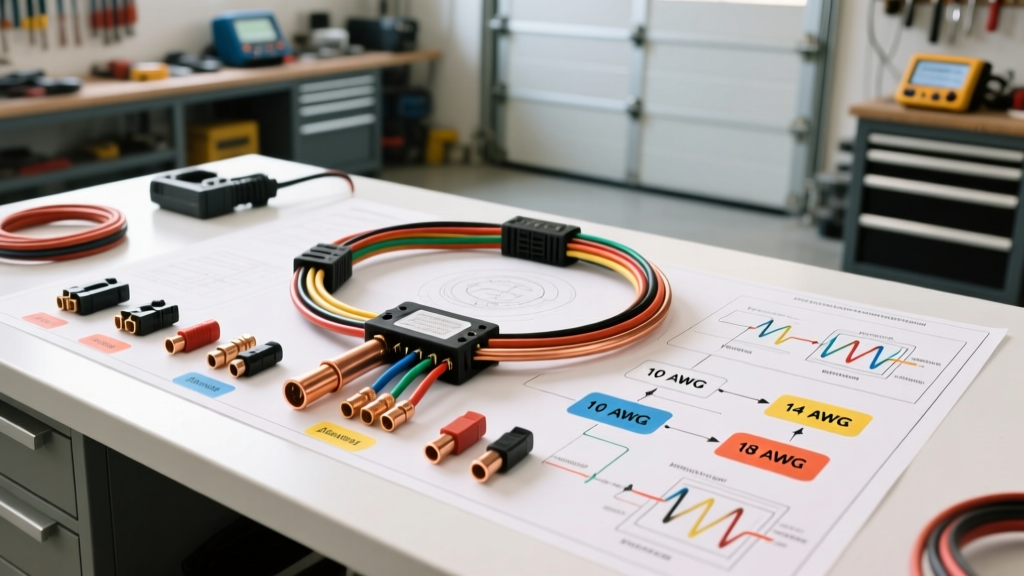
When determining the correct wire gauge for 12V runs, you must account for the total length of the circuit (positive feed + ground return). The chart below outlines maximum continuous ampacity and recommended maximum lengths to maintain a strict 3% voltage drop in a 12V DC system, utilizing standard copper automotive wire.
| AWG Size | Cross-Section (mm²) | Max Amps (Chassis) | Max Length @ 15A (3% Drop) | Max Length @ 30A (3% Drop) | Typical Automotive Application |
|---|---|---|---|---|---|
| 18 AWG | 0.82 | 6A | 3.5 ft | N/A | ECU Sensors, Relay Coils, LEDs |
| 16 AWG | 1.31 | 10A | 7.0 ft | N/A | Interior Lighting, Horns, Wipers |
| 14 AWG | 2.08 | 15A | 12.0 ft | 6.0 ft | Headlights, Fuel Pumps (Stock) |
| 12 AWG | 3.31 | 20A | 20.0 ft | 10.0 ft | Aftermarket Fuel Pumps, Winch Controls |
| 10 AWG | 5.26 | 30A | 32.0 ft | 16.0 ft | High-Draw Amplifiers, Radiator Fans |
| 8 AWG | 8.37 | 45A | 50.0 ft | 25.0 ft | Alternator Upgrades, Inverters |
| 4 AWG | 21.15 | 95A | N/A | 65.0 ft | Battery Relocation, Starter Cables |
Step 4: Inspect Physical Wiring and Connector Failure Modes
Upgrading to a thicker wire gauge is useless if the termination points act as high-resistance bottlenecks. According to TE Connectivity Automotive Interconnects data, terminal fretting, improper crimp compression, and environmental corrosion are leading causes of localized voltage drop.
- Crush vs. Crimp: Using non-ratcheting pliers on a Metri-Pack 280 terminal often results in a 'crush' rather than a proper cold-weld crimp. This leaves microscopic voids between the copper strands. Over time, thermal cycling causes the copper to oxidize (creating green copper oxide), drastically increasing resistance. A proper 12 AWG crimp should withstand a minimum pull force of 50 lbs per USCAR standards.
- SAE vs. AWG Discrepancy: Be aware that SAE J1128 wire has a slightly smaller copper cross-section than standard AWG wire for the same nominal gauge. For example, 10 AWG copper is 5.26 mm², while 10 SAE is roughly 4.90 mm². When calculating long runs, this discrepancy can push a marginal circuit over the 3% voltage drop threshold.
- Ground Side Neglect: Troubleshooters often focus solely on the 12V+ feed. However, the ground return path is equally critical. A factory 16 AWG ground wire spliced into a 12 AWG positive feed will still bottleneck the circuit. Always measure voltage drop on the ground side by placing the red probe on the accessory ground pin and the black probe directly on the negative battery terminal.
Step 5: Environmental Derating and Circuit Rectification
Wire ampacity ratings are typically based on a 20°C (68°F) ambient environment. In an engine bay, ambient temperatures near exhaust headers or turbochargers can easily exceed 105°C. Standard PVC-insulated wire (GXL) begins to degrade and its resistance increases at high temperatures. For under-hood 12V applications, you must use TXL or HDT cross-linked polyethylene wire, which is rated for 125°C to 150°C. Furthermore, you must apply a thermal derating factor: a 12 AWG wire rated for 20A in the cabin may only safely carry 14A in a 125°C engine bay.
To rectify a failing circuit, bypass the factory wiring entirely using a relay. This allows you to run heavy-gauge wire directly from the battery while using the factory low-current switch to trigger the relay coil.
ISO Mini Relay Pinouts and Wire Sizing Bypass
When installing a relay to bypass a factory headlight switch (which often uses inadequate 18 AWG wiring for high-draw H9 halogen bulbs), adhere to the standard ISO Mini Relay (Bosch-style) pin configuration:
- Pin 30 (Common/Battery): 12V+ direct from the battery via an inline fuse. Must match the heavy wire gauge required by the load (e.g., 12 AWG).
- Pin 87 (Normally Open): Output to the 12V+ accessory. Must match the heavy wire gauge of Pin 30.
- Pin 86 (Coil 12V+): Trigger wire from the factory switch. Because the relay coil only draws roughly 150mA, this can safely utilize the factory 18 AWG wire.
- Pin 85 (Coil Ground): Ground for the relay coil. Can be grounded locally to the chassis using 16-18 AWG wire.
- Pin 87a (Normally Closed): Not used in standard accessory bypass configurations. Leave insulated or cut back.
By systematically measuring voltage drop under load, calculating true operational amperage, and utilizing proper ratcheting crimp tools on high-temp SAE wire, you can permanently eliminate 12V accessory failures and ensure optimal electrical system performance.