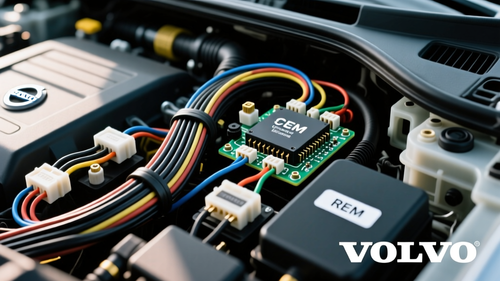
Understanding Volvo S60 Electrical Architecture
When diagnosing Volvo S60 electrical problems, it is crucial to understand that modern Volvos—particularly the highly popular P2 platform (2001–2009) and early P3 models (2011+)—do not use simple point-to-point wiring. Instead, they rely on a multiplexed Controller Area Network (CAN) bus system. This network allows various electronic control modules to share data over a single pair of twisted wires, drastically reducing the total copper weight in the vehicle.
For a beginner, this means a fault in one seemingly unrelated area (like a trunk latch sensor) can cause bizarre symptoms in another (like the dashboard gauges dropping out). To successfully troubleshoot these systems, you must abandon old-school 'test light' methods and adopt a systematic, multimeter-based diagnostic approach.
The Golden Rule: Never Use a Test Light on a CAN Bus
Before diving into specific Volvo S60 electrical problems, you must understand tool safety. Traditional 12V incandescent test lights draw significant current. If you accidentally probe a CAN data line (which operates at roughly 2.5 volts and low milliamperes) with a 12V test light, you will instantly backfeed voltage into the data bus, potentially frying the transceiver chips inside the Central Electronic Module (CEM) or the Engine Control Module (ECM).
Required Tools for S60 Diagnostics:
- Digital Multimeter (DMM): Must have a minimum 10-megohm input impedance and millivolt/milliamp resolution.
- Torx Bit Set: T25 and T30 are required for almost all Volvo interior module removal.
- Depinning Tools: Volvo uses specific TE Connectivity and Yazaki connectors. You will need 1.5mm and 2.8mm terminal release tools to safely extract wires without breaking the plastic housings.
- Wire Repair Supplies: Automotive-grade heat shrink with adhesive lining. Never use electrical tape under the dash, as the adhesive melts and creates a messy, unreliable bond.
Symptom-Cause-Fix Decision Tree: Top Volvo S60 Electrical Problems
Below is a beginner-friendly decision tree addressing the most frequent electrical failures reported by S60 owners. Use this to narrow down your diagnostic path before reaching for the wiring diagrams.
1. Parasitic Battery Drain (Battery Dies Overnight)
- Symptom: Vehicle starts fine if driven daily, but the battery is completely dead after sitting for 48 hours.
- Common Cause: Water ingress into the Central Electronic Module (CEM) or a Rear Electronic Module (REM) failing to enter 'sleep' mode.
- The Fix: Check the AC evaporator drain tube and sunroof drains. If clogged, water backs up and drips directly onto the CEM, located behind the passenger side kick panel (LHD models). Clean the drains, remove the CEM (using a T25 Torx), and inspect the circuit board for green copper corrosion. For REM issues, proceed to the parasitic draw test outlined below.
2. Tail Light 'Bulb Failed' Messages & Flickering
- Symptom: The Driver Information Module (DIM) displays 'Right/Left Tail Light Bulb Failed', but the bulb is new. Lights may flicker or stay on when the car is off.
- Common Cause: The Rear Electronic Module (REM), located in the left side of the trunk, suffers from cracked surface-mount device (SMD) resistors due to thermal cycling from bulb heat.
- The Fix: Remove the trunk trim. Unplug the REM connectors (press the locking tab and pull the lever). Open the REM casing and inspect the solder joints on the large SMD resistors. Reflow the solder using a temperature-controlled soldering iron. Do not simply swap in a used REM without cloning it via VIDA (Volvo's proprietary diagnostic software), as the REM is VIN-locked to the vehicle's configuration.
3. Dashboard Gauges Drop to Zero & Warning Lights Illuminate
- Symptom: Speedometer and tachometer drop to zero while driving, accompanied by ABS, SRS, or BCM warning lights.
- Common Cause: High-Speed CAN (HS-CAN) bus short or open circuit, often caused by chafed wiring near the steering column or a failing Brake Control Module (BCM).
- The Fix: Test the CAN bus termination resistance at the OBD2 port to determine if the network is intact or shorted.
Volvo S60 CAN Bus Wiring Specifications & Pinouts
To diagnose network communication faults, you must interface with the OBD2 diagnostic link connector (DLC). The S60 utilizes two primary CAN networks. Understanding the wire colors, gauges, and voltages is critical for accurate multimeter testing.
| OBD2 Pin | Network / Function | Wire Color (Typical) | Wire Gauge (AWG / mm²) | Expected Voltage (Ignition ON) |
|---|---|---|---|---|
| Pin 6 | HS-CAN High (High Speed) | Yellow | 20 AWG (0.5 mm²) | ~2.6V to 3.5V |
| Pin 14 | HS-CAN Low (High Speed) | Green | 20 AWG (0.5 mm²) | ~1.5V to 2.4V |
| Pin 3 | MS-CAN High (Medium Speed) | Yellow/Red | 20 AWG (0.5 mm²) | ~5.0V (or 12V idle) |
| Pin 11 | MS-CAN Low (Medium Speed) | Green/White | 20 AWG (0.5 mm²) | ~0.0V (or 12V idle) |
| Pin 16 | Battery Positive (Constant) | Red/White | 14 AWG (2.0 mm²) | 12.0V - 12.6V |
| Pins 4 & 5 | Chassis / Signal Ground | Black | 14 AWG (2.0 mm²) | 0.0V |
Note: Wire colors may vary slightly based on the exact model year and manufacturing plant. Always verify with a wiring diagram specific to your VIN.
Step-by-Step: Testing the HS-CAN Bus with a Multimeter
The High-Speed CAN bus connects critical modules like the ECM, TCM (Transmission), BCM (Brakes), and CEM. According to the SAE J2284 High-Speed CAN Standard, the network requires two 120-ohm terminating resistors placed at opposite ends of the bus to prevent signal reflection. Because these resistors are in parallel, a healthy network will read exactly 60 ohms.
- Preparation: Turn the ignition OFF and remove the key. Ensure all doors are closed and the hood is latched.
- Set the DMM: Turn your multimeter to the Ohms (Ω) setting. Select the lowest range (usually 200Ω).
- Probe the DLC: Insert your multimeter probes into OBD2 Pin 6 (CAN-H) and Pin 14 (CAN-L). Polarity does not matter for resistance testing.
- Read the Result:
- 60 Ohms (± 5 Ohms): The CAN bus wiring is intact, and both terminating resistors are present. The issue is likely internal to a specific module.
- 120 Ohms: One of the terminating resistors is missing, or there is an open circuit (broken wire) isolating one end of the network. Check the CEM and ECM connectors for backed-out pins or corrosion.
- 0 to 10 Ohms: There is a dead short between the CAN-H and CAN-L wires. This will take down the entire network. Look for pinched wiring under the dashboard or near the BCM in the engine bay.
For a deeper dive into network topology and differential signaling, the AA1CAR CAN Bus Diagnostics Guide provides excellent visual examples of oscilloscope waveforms versus multimeter averages.
Mastering the Volvo 'Sleep Mode' Parasitic Draw Test
One of the most misunderstood Volvo S60 electrical problems is the parasitic battery drain. Beginners often pull fuses immediately after turning the car off, which causes false readings. Volvo modules take a significant amount of time to power down and enter 'sleep' mode.
The Correct Parasitic Draw Procedure
- Wait for Sleep: After turning off the ignition and closing all doors (latch them manually with a screwdriver if the hood/trunk must be open for access), wait at least 20 to 40 minutes. You will hear the fuel pump prime and various relays click; eventually, the CEM will cut power to the interior bus. The sleep current should drop below 50 milliamps (0.05A).
- Setup the DMM: Set your multimeter to the 10A (Amp) setting. Move the red probe to the 10A port.
- Disconnect the Battery: Loosen the negative battery terminal clamp. Before pulling it off the post, place your multimeter probes in series: one on the negative post, one on the negative cable clamp. (Tip: Use a jumper wire to maintain power while disconnecting to prevent modules from waking up and throwing false codes).
- Remove the Jumper: Once the DMM is in series and reading the current, remove the jumper wire.
- Isolate the Fault: If the draw is high (e.g., 800mA), begin pulling fuses one by one. Crucial: Wait 2-3 minutes after pulling each fuse, as removing a fuse can wake up other modules on the same network branch. If pulling the CEM fuses in the passenger kick panel drops the draw to 30mA, you have isolated the fault to the CEM or a component directly powered by it.
Wire Repair and Connector Standards
When you locate a broken wire or a corroded pin, do not simply twist the wires together. The S60's CAN bus wires are twisted at a specific rate (typically 1 twist per inch) to cancel out electromagnetic interference (EMI). When repairing a 20 AWG (0.5 mm²) CAN wire:
- Use matching 20 AWG automotive cross-linked polyethylene (XLPE) wire.
- Maintain the twist rate as close to the repair point as possible.
- Use adhesive-lined marine-grade heat shrink to seal out moisture. The interior of a car experiences massive humidity swings, and standard solder joints will oxidize and create voltage drop over time.
- If a terminal is corroded inside a TE Connectivity housing, use the correct 1.5mm depinning tool to release the locking tang. Do not force it, or you will shatter the plastic housing, necessitating a full pigtail replacement.
Summary and Further Resources
Diagnosing Volvo S60 electrical problems does not require a dealership subscription if you understand the fundamental architecture. By respecting the CAN bus, utilizing a high-impedance multimeter, and allowing the vehicle's modules adequate time to enter sleep mode, you can accurately pinpoint CEM water damage, REM solder faults, and network shorts. Always verify your findings against the official OBD-II Connector Pinout Specifications before applying power or ground to any diagnostic port pin.