Introduction to Home-Built RV Electrical Systems
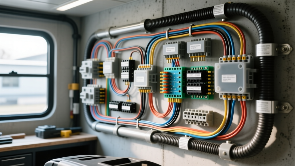
When troubleshooting electrical problems in home-built RV conversions, skoolies, and custom camper vans, technicians must navigate the complex intersection of automotive 12V DC architecture and residential 120V AC systems. Unlike standard passenger vehicles, a home-built motorhome relies on a dual-voltage ecosystem. The DC side handles engine starting, chassis lighting, and massive inverter loads, while the AC side manages shore power inputs, automatic transfer switches (ATS), and household appliances. Faults in these systems rarely exist in isolation; a poor DC chassis ground can cause AC GFCI nuisance tripping, and an undersized inverter cable can mimic a failed compressor on an AC rooftop unit. This guide provides a systematic, expert-level diagnostic workflow for identifying and resolving dual-voltage wiring faults in mobile residential platforms.
Safety Protocols: Lockout/Tagout for Dual-Voltage Platforms
Before connecting a multimeter to any terminal block, establish a strict lockout/tagout (LOTO) protocol. Home-built RVs present unique arc flash and electrocution hazards.
- DC Isolation: Disconnect the negative terminal of the main battery bank first. Install a high-amperage battery disconnect switch (rated for the total inverter load, typically 500A continuous for a 3000W inverter) to safely isolate the DC bus.
- AC Isolation: Unplug the shore power cord. Turn off all AC breakers in the sub-panel. Verify zero voltage at the ATS input using a CAT III rated digital multimeter (DMM).
- Inverter Capacitor Discharge: High-frequency inverters contain large DC bus capacitors that can hold lethal 120V+ DC charges long after battery disconnection. Turn the inverter on with no load to drain capacitors, then wait 10 minutes before touching AC output terminals.
Phase 1: 12V DC Battery Bank & Inverter Input Diagnostics
The most common failure mode in home RV conversions is excessive voltage drop on the inverter DC feed. When an inverter pulls 200A to run a microwave, a 0.5V drop drops the inverter input below its low-voltage cutoff (typically 10.5V), causing an immediate shutdown. This is often misdiagnosed as a bad inverter or weak batteries.
Inverter Input Wire Sizing & Torque Specifications
Never use solid copper wire or standard automotive primary wire for inverter feeds. Vibrations in a mobile environment will cause solid wire to fatigue and snap. Always use Class K or Type 3135 stranded copper welding cable, preferably tinned to resist oxidation in high-humidity environments.
| Inverter Size (12V Nominal) | Max DC Draw | Min AWG (up to 5ft) | Min AWG (up to 10ft) | Lug Torque Spec |
|---|---|---|---|---|
| 1000W | 110A | 2 AWG | 1/0 AWG | 75 in-lbs |
| 2000W | 220A | 1/0 AWG | 2/0 AWG | 120 in-lbs |
| 3000W | 330A | 2/0 AWG | 4/0 AWG | 150 in-lbs |
The Millivolt Drop Test Procedure
Do not rely on standard voltage readings to find bad connections; use the millivolt (mV) drop test under load as recommended by SAE J1171 marine and RV electrical standards.
- Set your DMM to the DC millivolt scale.
- Place the red probe on the battery post (not the clamp) and the black probe on the inverter positive terminal.
- Force a heavy DC load (e.g., turn on the coffee maker via the inverter).
- A healthy circuit should show a drop of less than 3% of system voltage (approx. 0.36V or 360mV on a 12V system). If you read 0.60V (600mV), you have high resistance, likely due to a loose crimp, oxidation, or an undersized fuse block.
Phase 2: 120V AC Shore Power & Transfer Switch Diagnostics
AC faults in home conversions usually stem from improper shore power inlet wiring, miswired ATS units, or overloaded sub-panels. Understanding the exact pinout of your shore power connector is critical for safe troubleshooting.
Shore Power Connector Pinouts & Color Codes
Residential wiring standards dictate specific color codes that must be strictly adhered to inside the RV's AC panel. Black or Red is Hot (Line), White is Neutral, and Green or Bare Copper is Equipment Ground.
| Connector Type | Ampacity | Pin Configuration | Voltage / Phases |
|---|---|---|---|
| NEMA TT-30P (RV Standard) | 30A | 1 Hot (X), 1 Neutral (W), 1 Ground (G) | 120V Single Phase |
| NEMA 14-50P (Large RV) | 50A | 2 Hot (X, Y), 1 Neutral (W), 1 Ground (G) | 120V/240V Split Phase |
Diagnosing ATS (Automatic Transfer Switch) Failures
If your RV has both a generator and shore power, an ATS routes the correct 120V source to the breaker panel. A common failure mode is the ATS failing to switch, or chattering loudly.
- Chattering Relay: Usually caused by low generator RPM (producing AC voltage below the ATS threshold, typically 105V) or a failing neutral connection in the generator's junction box.
- Shore Power Dead on Arrival: Check the TT-30 inlet. The spade terminals on cheap aftermarket inlets frequently overheat and melt due to loose tension. Inspect the back of the inlet for brown discoloration on the plastic housing. Replace with a marine-grade, locking shore power inlet (e.g., Marinco 30A) using 10 AWG stranded copper wire.
Phase 3: Grounding & Bonding Failures (The #1 Culprit)
The most dangerous and confusing faults occur when installers misunderstand the difference between DC chassis grounding and AC safety grounding. For comprehensive safety codes governing these bonds, refer to the NFPA 1192 Standard on Recreational Vehicles.
The Neutral-Ground Bond Dilemma
In a standard residential home, the neutral and ground are bonded at the main service panel. In an RV, the neutral and ground must never be bonded at the sub-panel. They are bonded only at the source (the shore power pedestal or the generator).
Real-World Failure Mode: A DIY builder installs a 3000W inverter/charger and bonds the neutral to the ground inside the RV's AC sub-panel to 'make the GFCI outlets work'. When they plug into shore power, the shore pedestal's GFCI breaker trips instantly because the neutral current is returning via the ground wire, creating an imbalance.
The Fix: Ensure the RV AC sub-panel has isolated neutral and ground bus bars. If using an inverter with an internal automatic Neutral-Ground relay (like many Victron or Magnum models), ensure the inverter is configured as a 'Sub-Panel' or 'UPS' mode so it only bonds N-G when operating off-grid, and opens the bond when shore power is detected. Consult the Victron Energy Wiring Unlimited guide for exact relay logic configurations.
Systematic Troubleshooting Decision Tree
Follow this diagnostic sequence when an appliance fails to operate or a breaker trips repeatedly:
- Symptom: Inverter shuts down under heavy AC load.
Check: DC voltage drop under load. Fix: Upgrade DC cabling to 2/0 AWG, clean battery terminals with a wire brush, apply dielectric grease, and re-torque to 120 in-lbs. - Symptom: Shore power GFCI trips immediately upon plug-in.
Check: Neutral-Ground bond in the RV sub-panel or inverter. Fix: Separate N and G buses. Verify inverter internal relay settings. - Symptom: AC rooftop unit hums but compressor won't start on inverter.
Check: Inverter surge capacity and AC waveform. Fix: Ensure inverter is a Pure Sine Wave (PSW) model. Modified Sine Wave (MSW) inverters cause severe overheating and starting torque loss in AC induction motors. Install a soft-start capacitor kit on the AC unit to reduce locked-rotor amperage (LRA) draw. - Symptom: 12V LED lights flicker when the water pump engages.
Check: DC voltage sag and shared ground paths. Fix: Run a dedicated 12 AWG ground wire for the LED driver directly to the main DC busbar, avoiding the chassis ground which carries high motor-return current from the water pump.
Conclusion
Successfully diagnosing electrical faults in home-built motorhomes requires a dual mindset. You must apply rigorous automotive DC voltage-drop testing techniques while strictly adhering to residential AC safety and bonding codes. By utilizing the correct stranded, tinned copper wiring, adhering to precise torque specifications, and understanding the critical nature of the Neutral-Ground bond, you can build and troubleshoot an RV electrical system that is both resilient on the road and safe for residential living.