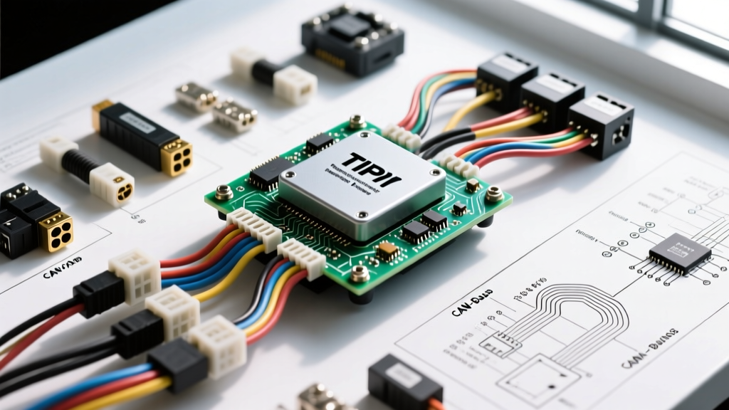
Introduction to WK Generation Multiplexing & TIPM Architecture
When diagnosing Jeep Grand Cherokee electrical problems, particularly in the 2005-2010 (WK) generation, technicians must shift their mindset from traditional point-to-point wiring to multiplexed network diagnostics. The heart of the WK electrical system is the Totally Integrated Power Module (TIPM). The TIPM replaces the traditional under-hood fuse block and integrates solid-state relays, the front control module (FCM), and the gateway for the Controller Area Network (CAN-C and CAN-B buses).
Because the TIPM acts as the central nervous system for power distribution and data routing, a single corroded pin or failing ground splice can cascade into multiple seemingly unrelated symptoms—from intermittent stalling and dead batteries to total loss of instrument cluster communication. This step-by-step troubleshooting flow is designed to isolate TIPM, CAN bus, and grounding faults using systematic voltage drop testing and pin-level verification.
Step 1: Data Link Connector (DLC) Triage & CAN-C Verification
Before unbolting any modules, you must verify the integrity of the high-speed CAN-C bus at the OBD-II Data Link Connector (DLC). The CAN-C bus operates at 500 kbps and handles critical powertrain and chassis modules (PCM, TCM, ABS, ORC).
- Set your digital multimeter (DMM) to the Ohms (Ω) setting.
- With the vehicle completely powered down and the key removed, measure the resistance between DLC Pin 6 (CAN-C High) and Pin 14 (CAN-C Low).
- Specification: You must read exactly 60 ohms. This confirms that both the 120-ohm terminating resistor in the PCM and the 120-ohm resistor in the TIPM are intact and the bus is continuous.
- If you read 120 ohms, one half of the bus is open. If you read near 0 ohms, the CAN-H and CAN-L wires are shorted together.
For a deeper understanding of network topology and termination requirements, refer to the SAE International J1939 CAN Bus Standards. If the DLC resistance checks out, proceed to physical inspection of the TIPM connectors.
Step 2: Inspect TIPM C1 & C3 Connectors for Pin Fretting
A primary cause of Jeep Grand Cherokee electrical problems is 'pin fretting'—micro-movements between male and female terminals that wear away the tin plating, leading to oxidation and high resistance. The C1 (Black, 26-way) and C3 (Gray, 26-way) connectors carry the main CAN bus trunks and high-current power feeds.
TIPM C1 Connector Pinout & Wire Specifications
Disconnect the negative battery cable before releasing the C1 connector locking lever. Inspect the following critical pins for green/white corrosion or pushed-back terminals:
| Pin | Circuit Function | Wire Color | AWG Size | Diagnostic Note |
|---|---|---|---|---|
| 13 | CAN-C (+) High | White/Dark Green (WT/DG) | 22 AWG | Twisted pair with Pin 14. Check for shorts to ground. |
| 14 | CAN-C (-) Low | White/Light Green (WT/LG) | 22 AWG | Must show 2.5V at rest with KOEO. |
| 1 | Fused B+ (Main Feed) | Red (RD) | 10 AWG | Common failure point for high-amp draw melting. |
| 22 | Fused Ignition Run/Start | Dark Blue/White (DB/WT) | 18 AWG | Powers PCM and TCM logic. Loss causes stalling. |
| 8 | CAN-B (+) High | White/Dark Green (WT/DG) | 22 AWG | Low-speed bus for body modules (Radio, HVAC). |
Correction Protocol: If corrosion is present, do not simply scrape the pins. Use a specialized electrical contact cleaner, followed by Mopar Dielectric Grease (Part #05013471AA) applied directly to the female terminal cavities before reseating. The grease displaces moisture and prevents future fretting.
Step 3: Perform Voltage Drop Tests on High-Current Grounds
The WK Grand Cherokee relies heavily on ground splices, specifically G200 (Left A-pillar kick panel) and G300 (Right A-pillar kick panel). A compromised G200 will cause the CAN-C bus voltage to float, resulting in U-code communication faults and erratic gauge cluster behavior.
According to the Fluke Voltage Drop Testing Guide, measuring resistance on a ground wire is useless for detecting high-resistance faults under load. You must measure voltage drop while the circuit is active.
G200 Ground Testing Procedure
- Set your DMM to the DC Millivolt (mV) scale.
- Connect the red lead to the negative battery post (not the clamp).
- Connect the black lead to the bare metal grounding stud of G200.
- Turn the ignition ON and activate high-load accessories (headlights high beam, HVAC blower on high).
- Specification: The voltage drop across a 10 AWG ground wire and splice must be less than 100 mV (0.1V). If your reading exceeds 200 mV, the ground eyelet is corroded, or the wire strands are broken internally. Remove the G200 nut, wire-brush the stud and eyelets to bare metal, and re-torque to 10 Nm (88 in-lbs).
Step 4: Parasitic Draw Isolation & Sleep Cycle Flow
A dead battery is one of the most frequent Jeep Grand Cherokee electrical problems. The WK generation features complex module sleep cycles. If a module fails to enter 'sleep' mode, the parasitic draw will drain the battery overnight.
Understanding the IOD Fuse & Sleep Cycle
The TIPM contains an Ignition Off Draw (IOD) fuse mechanism. When the vehicle is turned off, the TIPM waits for a specific CAN bus 'sleep' message. The modules take up to 20 minutes to completely power down their internal logic boards. Testing parasitic draw before the 20-minute mark will yield false-high readings.
- Target Parasitic Draw: Less than 35 mA (0.035A) after 20 minutes.
- Common Culprits: Wireless Control Module (WCM) failing to recognize key removal, aftermarket radio CAN-bus adapters keeping the CAN-B bus awake, or a shorted TIPM internal solid-state relay.
Isolation Trick: Instead of pulling fuses one by one (which wakes the modules back up by interrupting the B+ feed), use a clamp-on milliammeter or an inline DMM with a 'wake-up' bypass switch. Monitor the current over 25 minutes. If the draw remains above 500 mA after the sleep cycle, systematically isolate the CAN-B and CAN-C bus trunks at the TIPM C1 and C3 connectors to see if the network activity ceases.
Symptom-Cause-Fix Decision Tree
Use this rapid-reference decision tree to pinpoint specific WK Grand Cherokee electrical failures based on customer complaints and scan tool data.
- Symptom: Intermittent Stalling while driving, accompanied by 'ESP BAS' and 'Check Engine' lights.
- Cause: Loss of CAN-C communication between PCM and TIPM due to pin fretting at C1-13/14, or voltage drop at PCM Ground G105.
- Fix: Verify 60 ohms at DLC. Inspect TIPM C1 pins 13 & 14. Apply dielectric grease. Check G105 on the engine block for corrosion.
- Symptom: Interior lights flicker, power windows operate sluggishly, and U0140 (Lost Comm with BCM) is stored.
- Cause: High resistance at Ground G200 or G300 causing the CAN-B bus reference voltage to float above the 6.5V threshold.
- Fix: Perform voltage drop test on G200/G300. Clean eyelets and body contact points. Verify B+ feed to the Junction Block under the dash.
- Symptom: Battery dead every morning. Draw reads 450 mA after 30 minutes.
- Cause: A module is holding the CAN-B bus awake. Often caused by a faulty radio, HVAC control head, or a shorted WCM (SKIM module).
- Fix: Use a PicoScope or advanced DMM to monitor CAN-H and CAN-L waveforms at the DLC. If the bus shows continuous 0-5V square waves after 20 minutes, pull the C3 connector (CAN-B trunk) at the TIPM to see if the bus goes to sleep. If it does, isolate downstream CAN-B nodes one by one.
Expert Tips & Preventative Maintenance
To prevent recurring Jeep Grand Cherokee electrical problems, always apply a thin layer of dielectric grease to all exterior TIPM connectors and ground eyelets during reassembly. The WK engine bay is prone to moisture ingress near the cowl, which accelerates galvanic corrosion between the copper terminals and the aluminum TIPM housing. Furthermore, when replacing a TIPM, remember that the unit is VIN-locked and contains the vehicle's skew number and mileage data. A used TIPM from a junkyard will require configuration via a dealer-level scan tool (like the WiTECH) to sync with the PCM and WCM, otherwise the vehicle will experience a crank-no-start condition due to the Sentry Key Immobilizer System (SKIS) mismatch. For official module programming procedures and TSB references, consult Mopar Technical Service Bulletins.