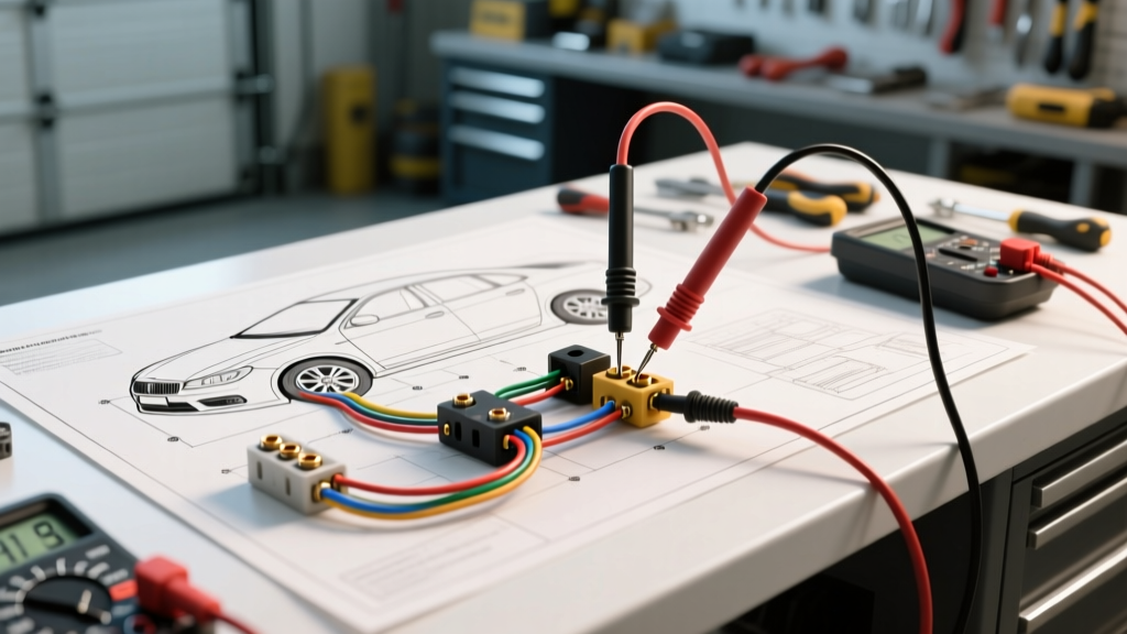
Essential Diagnostic Tool Installation & Safety Prep
Modern vehicles rely on complex multiplexed networks, including CAN-bus and LIN-bus architectures, making traditional troubleshooting methods obsolete. Using a standard incandescent test light on a modern 18 AWG sensor circuit can draw excessive current, instantly frying a solid-state control module or blowing a micro-fuse. To accurately determine how to diagnose electrical problems in a car, you must first shift your mindset from simple continuity testing to dynamic circuit analysis under load. This requires the proper installation of diagnostic test equipment, fused jumper harnesses, and precision back-probing tools.
Before touching a wiring harness, a professional technician must install and configure a high-impedance digital multimeter (DMM) with a minimum 10-megohm input impedance. According to Fluke Automotive Troubleshooting guidelines, using a low-impedance meter can load down sensitive 5-volt reference circuits, providing false diagnostic data. Furthermore, you must fabricate and install a set of diagnostic fused jumper wires to safely bypass suspect harness sections without risking a vehicle fire.
Fabricating and Installing a Diagnostic Jumper Harness
To safely route power or ground during a diagnostic test, never use generic household wire. You must install jumper harnesses built from automotive-grade cross-linked polyethylene wire.
- 10 AWG TXL Wire: Use for high-current feeds like fuel pump relays, cooling fan circuits, and starter solenoid bypasses. TXL (Thin-wall Cross-Linked) insulation withstands under-hood temperatures up to 125°C.
- 14 AWG GXL Wire: Ideal for standard 12V accessory feeds, headlamp circuits, and power window motor bypasses.
- 18 AWG TXL Wire: Strictly reserved for low-current sensor feeds, 5V reference testing, and CAN-bus diagnostic breakout installations.
When installing terminal ends on your jumper harnesses, use a ratcheting crimp tool to ensure a gas-tight connection. Soldering is strictly prohibited in automotive vibration environments per SAE J1113 standards, as solder wicks into the wire strands, creating a rigid stress point that will eventually snap under engine vibration. Finish the installation by sealing the crimp barrel with dual-wall, adhesive-lined heat shrink tubing to prevent moisture-induced galvanic corrosion.
Step-by-Step: How to Diagnose Electrical Problems in a Car
The most reliable method to find high-resistance faults, corroded bulkhead connectors, or failing ground planes is the voltage drop test. Unlike a continuity test, which only measures resistance on a dead circuit, a voltage drop test evaluates the circuit dynamically while current is flowing under a real-world load.
Phase 1: Establishing a Known-Good Ground Reference
The most common diagnostic error is trusting the vehicle's chassis as an absolute ground. Paint, powder coating, and rust can introduce severe resistance. Before beginning, install a dedicated 10 AWG ground jumper directly from the negative battery post to a clean, bare-metal point on the engine block or the specific component's housing. This eliminates the vehicle's chassis ground from your test equation, ensuring your DMM reads only the resistance of the circuit you are actively diagnosing.
Phase 2: Executing the Voltage Drop Test Protocol
Set your DMM to DC Volts. To test the power side of a circuit, connect the red probe to the battery positive terminal and the black probe to the power input pin at the component (e.g., the fuel pump connector). Turn the circuit ON to draw current. The DMM will display the exact amount of voltage being consumed (dropped) by the wiring, connectors, and switches between your two probe points.
Consult the following SAE-derived specification chart to determine if your installed wiring is failing:
| Circuit Type | Maximum Allowable Voltage Drop | Common Failure Points |
|---|---|---|
| Battery Positive to Starter Motor | 0.20V (200mV) | Corroded cable lugs, failing ignition switch contacts |
| Engine Block to Chassis Ground | 0.10V (100mV) | Braided ground straps, painted engine-to-frame bolts |
| Standard 12V Accessory Feed (e.g., Headlamps) | 0.50V (500mV) | Dimmer switches, oxidized Metri-Pack terminals |
| Low Current Sensor Ground (e.g., MAF, O2 Sensors) | 0.05V (50mV) | Spliced grounds, ECM internal ground driver faults |
As noted by AA1Car's technical library on voltage drop testing, if your reading exceeds these thresholds, the fault lies exactly between your two probe points. You must move the probes closer together, isolating each connector and splice, until the excessive voltage drop disappears.
Parasitic Draw Test Equipment Installation
Diagnosing a dead battery requires measuring the vehicle's sleep-state current draw. Modern vehicles with CAN-bus networks can take up to 45 minutes to enter 'sleep mode,' drawing anywhere from 2 to 5 amps during the shutdown sequence. If you simply pull the negative battery cable and install your multimeter in series, the sudden loss of power will force all modules to reboot, and the initial 5-amp inrush will instantly blow your DMM's internal 10A fuse.
The Parallel Bypass Switch Installation Method
To protect your equipment and accurately capture the sleep-state draw, you must install a parallel bypass circuit before disconnecting the battery.
- Install the Bypass Jumper: Before loosening the negative battery terminal, connect a heavy-duty jumper cable (or a 10 AWG fused jumper) between the negative battery post and the disconnected negative cable clamp. This maintains continuous power to the vehicle's networks.
- Install the Multimeter: Set your DMM to the 10A or Amp setting. Connect the red lead to the negative cable clamp, and the black lead to the negative battery post. Your meter is now installed in parallel with the bypass jumper.
- Initiate Sleep Mode: Remove the bypass jumper. All current is now forced to flow through the multimeter. Close all doors, remove the key, and wait for the vehicle's modules to power down. You will watch the DMM display drop from several amps down to the target sleep specification (typically 30mA to 50mA for modern vehicles).
- Isolate the Fault: If the draw remains high (e.g., 1.2A), begin pulling fuses one by one. When the draw suddenly drops to the 30mA baseline, the circuit you just disabled contains the parasitic drain.
Back-Probing Modern Automotive Connectors
To diagnose electrical problems in a car without piercing wire insulation (which invites moisture and copper oxidation), you must install back-probe pins into the rear of the connector cavities. Using the wrong probe size will permanently spread the terminal tension fingers, causing intermittent connection failures later.
- GM Metri-Pack 280 Series: Use a dedicated 0.280-inch flat back-probe pin. These are commonly found on GM powertrain sensors and ABS modules.
- Delphi Weather-Pack: Use a round, tapered probe. These connectors feature a silicone weather seal that requires a rounded tip to slip past without tearing the seal.
- Deutsch DT Series: Common in heavy-duty and off-road applications. You must use a specialized Deutsch insertion tool to bypass the rear grommet and contact the 16 or 12 AWG terminal barrel.
By properly installing your test equipment, fabricating safe jumper harnesses, and strictly adhering to dynamic voltage drop protocols, you transform guesswork into a systematic, scientifically verifiable diagnostic process. This methodology ensures you replace failed components, rather than throwing expensive parts at complex electrical gremlins.