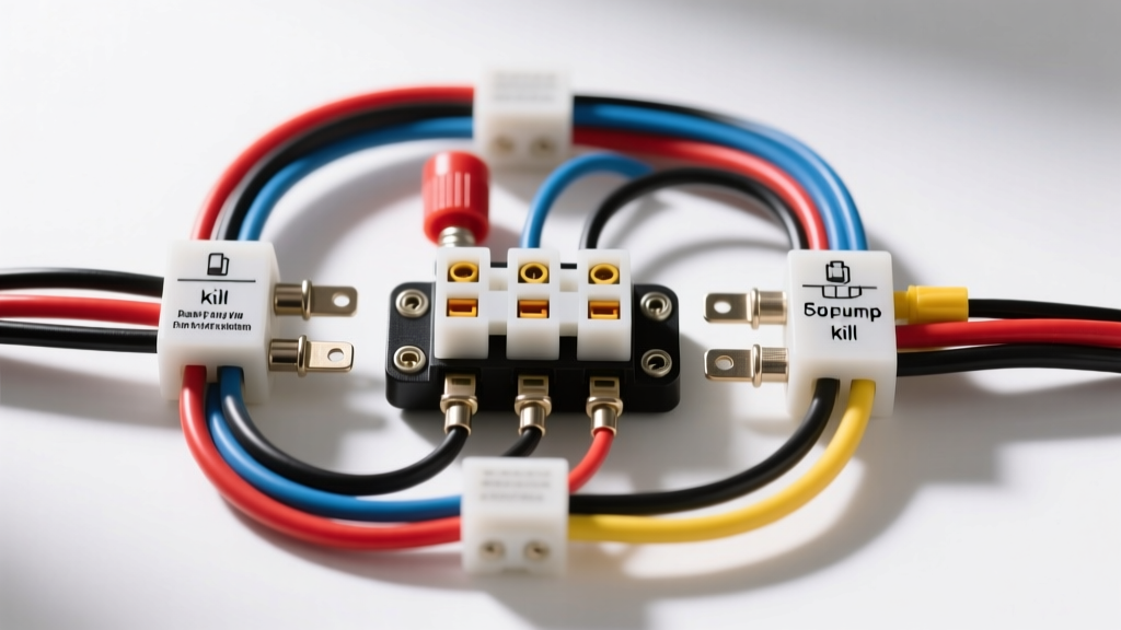
The Role of ISO Relays in Vehicular Fire Safety Systems
When integrating life-safety and fire suppression systems into RVs, overland expedition vehicles, and motorsport platforms, understanding fire alarm relay wiring diagrams is non-negotiable. Unlike standard building fire alarms governed strictly by NFPA 72, vehicular fire alarm and suppression modules must interface directly with high-current automotive circuits. These systems are designed to detect thermal anomalies or manual triggers and immediately execute critical safety protocols: killing the fuel pump, isolating the main battery solenoid, and triggering exterior alert lighting and horns.
Because fire alarm control modules output low-current logic signals (typically under 2 amps), they cannot directly switch high-amperage vehicle loads. Attempting to do so will instantly fry the module's internal PCB. Instead, we use automotive-grade Bosch-style ISO Mini relays to bridge the gap between the low-current alarm trigger and the high-current vehicle harness. This guide provides a complete technical walkthrough of the wiring diagrams required to safely implement these life-saving circuits.
System Architecture: Interfacing Fire Alarms with Vehicle Harnesses
A robust vehicular fire safety system relies on two primary relay circuits. The first is the Isolation and Kill Circuit, responsible for cutting power to the fuel pump and dropping the main battery disconnect solenoid. The second is the Alert and Lighting Circuit, which powers exterior LED light bars, marker lights, and the vehicle horn to warn bystanders and pit crews of a fire event. Both circuits utilize standard 4-pin and 5-pin ISO 7588 relays, but their pin configurations and fail-safe logic differ significantly.
According to the NFPA 1192 Standard on Recreational Vehicles, any automated shut-off system must default to a safe state in the event of a total electrical failure. Therefore, our relay wiring diagrams prioritize 'normally closed' (NC) logic for fuel delivery where applicable, or rely on latching relays for battery isolation.
Walkthrough 1: Fuel Pump Cut-Off and Battery Isolation Circuit
The most critical function of the fire alarm system is stopping the flow of combustible fuel and removing electrical energy from the engine bay. For this, we use a 5-pin ISO Mini relay (Terminals 30, 85, 86, 87, and 87a) configured as a normally closed kill switch for the fuel pump, alongside a heavy-duty continuous duty solenoid for battery isolation.
5-Pin Relay Pinout and Wire Routing
| Terminal | Function | Wire Color (SAE Std) | AWG Size | Connection Point |
|---|---|---|---|---|
| 30 | Common (COM) | Red | 10 AWG | Ignition-switched 12V+ Feed (Fuel Pump Relay Feed) |
| 87a | Normally Closed (NC) | Yellow | 10 AWG | Downstream to Fuel Pump Power Wire |
| 87 | Normally Open (NO) | Orange | 14 AWG | Battery Isolation Solenoid Trigger |
| 86 | Coil Positive | Blue | 14 AWG | Fire Alarm Module 'Kill' Output |
| 85 | Coil Negative | Black | 14 AWG | Chassis Ground (Ring Terminal) |
Circuit Logic: During normal operation, the relay coil (85/86) is unenergized. Power flows from Terminal 30 to Terminal 87a, allowing the fuel pump to run. When the fire alarm module detects a fault, it sends a 12V+ signal to Terminal 86. The coil energizes, snapping the internal contact away from 87a (killing the fuel pump) and connecting 30 to 87. This secondary connection sends a 12V+ trigger to the vehicle's main battery isolation solenoid, physically disconnecting the battery from the chassis harness to prevent electrical fires.
Walkthrough 2: Exterior Alert Lighting and Horn Trigger Circuit
Once the vehicle is immobilized, the system must alert the surroundings. This requires switching high-draw exterior lighting (like a 40-inch LED light bar or roof strobes) and a 120dB air horn. We utilize a standard 4-pin ISO relay for this lighting circuit, drawing power directly from an auxiliary fuse block rather than the ignition circuit, ensuring the alerts function even if the main battery is isolated.
4-Pin Lighting Relay Configuration
- Terminal 30 (Power In): 12 AWG Red wire connected to the Auxiliary Battery Fuse Block (protected by a 30A ATO fuse).
- Terminal 87 (Power Out): 12 AWG White wire splitting to the exterior LED light bar relay triggers and the horn relay.
- Terminal 86 (Coil +): 14 AWG Green wire connected to the Fire Alarm Module 'Strobe/Alert' output.
- Terminal 85 (Coil -): 14 AWG Black wire to a clean, bare-metal chassis ground.
By wiring the lighting circuit to the auxiliary battery bank, the exterior alerts remain fully operational even if the primary engine bay fire has triggered the main battery disconnect solenoid outlined in Walkthrough 1.
Critical Protection: Flyback Diodes and Inductive Kickback
A common failure point in aftermarket fire alarm relay wiring diagrams is the omission of flyback diodes. When the fire alarm module cuts power to the relay coil (Terminals 85 and 86), the collapsing magnetic field inside the relay generates a massive reverse voltage spike (inductive kickback), often exceeding 100 volts. This spike travels backward into the fire alarm module's low-voltage logic board, destroying the output transistor.
The Fix: You must solder a 1N4004 rectifier diode across the relay coil terminals (85 and 86). The silver band on the diode must point toward Terminal 86 (the 12V+ positive side). This creates a closed loop that safely dissipates the voltage spike within the relay circuit, protecting the expensive fire alarm control module. For compliance with SAE J1113 electromagnetic compatibility standards, suppressing this transient voltage is also necessary to prevent EMI interference with the vehicle's ECU and CAN bus networks.
Wire Sizing, Terminal Crimping, and Environmental Sealing
Vehicular environments—especially in off-road RVs and motorsports—subject wiring to extreme vibration, thermal cycling, and moisture. Standard PVC wire and plastic butt connectors will fail. Refer to the specification chart below for proper material selection:
| Component | Specification | Reasoning |
|---|---|---|
| Wire Type | Marine-Grade Tinned Copper (THHN or TXL) | Tinning prevents galvanic corrosion and black-wire disease in humid environments. |
| Terminals | Open-Barrel U-Crimp or Nylon Insulated Ring | Provides superior pull-out strength and vibration resistance compared to closed-barrel. |
| Sealing | Dual-Wall Adhesive Heat Shrink (3:1 ratio) | The inner meltable adhesive creates a waterproof seal over the crimp barrel, preventing moisture wicking. |
| Relay Socket | Sealed IP67 Relay Harness with Locking Tab | Prevents the relay from vibrating out of the socket during off-road transit or track use. |
Real-World Troubleshooting: Voltage Drop and False Triggers
When debugging a newly installed fire alarm relay system, technicians frequently encounter two specific issues:
1. The Relay Chatters or Fails to Fully Engage
Cause: Voltage drop on the control side (Terminals 85 and 86). If the fire alarm module is located in the rear of an RV and the relay is in the front engine bay, the 14 AWG trigger wire may suffer significant voltage drop over a 25-foot run. If the voltage at Terminal 86 drops below 9V, the ISO relay coil will not generate enough magnetic force to fully seat the internal contact, resulting in high resistance and arcing at Terminal 30/87.
Fix: Measure voltage at the relay socket with a digital multimeter while the alarm is triggered. If voltage is below 11.5V, upgrade the trigger wire to 12 AWG, or install a secondary 'booster' relay closer to the alarm module.
2. False Alarm Triggers During Engine Cranking
Cause: Voltage transients and electrical noise generated by the starter motor are feeding back into the fire alarm sensor wiring, tricking the module into thinking a thermal event has occurred.
Fix: Ensure all fire sensor shielded cables are routed at least 6 inches away from high-current ignition wires and alternator outputs. Additionally, verify that the relay flyback diodes are correctly oriented to clamp EMI noise, as recommended in the Littelfuse Automotive Relay Application Guide.
Summary
Designing and executing accurate fire alarm relay wiring diagrams requires a deep understanding of both life-safety logic and high-current automotive electrical principles. By utilizing 5-pin ISO relays for fuel and battery isolation, 4-pin relays for auxiliary alert lighting, and mandatory flyback diode protection, you ensure that the vehicle's fire suppression system operates flawlessly when seconds count. Always adhere to marine-grade crimping standards and verify voltage at the relay coil to guarantee long-term reliability in harsh vehicular environments.