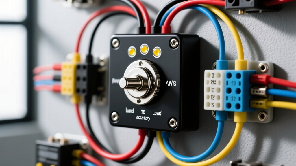
Why You Must Use a Relay with Your Light Bar Rocker Switch
When installing off-road lighting, beginners often make the critical mistake of attempting to route the full amperage of the lighting circuit directly through the dashboard. A standard 50-inch LED light bar can draw between 15 and 20 amps at 12 volts. While many marine-grade switches are rated for 20 amps, pushing that much current through the small copper contacts of a dashboard switch and routing thick 10 AWG or 12 AWG wire through the vehicle's firewall and steering column is a severe fire hazard. Furthermore, long wire runs to the dash introduce significant voltage drop, resulting in dimmer lights and excess heat generation at the switch terminals.
The proper methodology is to use your light bar rocker switch solely as a low-amperage trigger mechanism. By wiring the switch to control the electromagnetic coil of a 30A or 40A automotive relay, you keep the high-current load in the engine bay. The switch will only need to carry roughly 150 milliamps (0.15A) to activate the relay coil, ensuring your dashboard wiring remains cool, safe, and compliant with SAE J1128 low-tension primary cable standards.
Anatomy of a Standard 5-Pin DPST Rocker Switch
Most premium off-road lighting kits include a 5-pin DPST (Double Pole, Single Throw) rocker switch, often modeled after the industry-standard Carling V-Series contours. Understanding the terminal layout is the most crucial step for beginners. The pins are typically numbered on the back of the switch housing.
| Pin Number | Terminal Type | Function & Wiring Destination | Recommended Wire Color |
|---|---|---|---|
| Pin 2 | Line (Power In) | Receives 12V+ from an ignition-switched fuse tap. | Red (18 AWG) |
| Pin 3 | Load (Power Out) | Sends 12V+ to Relay Pin 86 when switched ON. | Blue (18 AWG) |
| Pin 6 | LED Ground | Grounds the internal indicator LED. | Black (18 AWG) |
| Pin 7 | LED Power | Receives 12V+ to illuminate the switch face (dash dimmer or ignition). | White (18 AWG) |
| Pin 8 | Secondary LED | Optional upper indicator LED (often left empty on single-LED switches). | N/A |
Note: Always verify your specific switch pinout with the manufacturer's datasheet, such as the Carling Technologies V-Series Guide, as cheap overseas clones occasionally swap the Line and Load terminals.
AWG Wire Sizing and Fuse Selection Chart
Using the correct American Wire Gauge (AWG) and matching it to the proper inline fuse or fuse tap is non-negotiable. Undersized wire will melt before the fuse blows, potentially igniting the vehicle's interior trim.
| Circuit Segment | Current Draw | Wire Gauge (AWG) | Overcurrent Protection |
|---|---|---|---|
| Switch Pin 2 (Ignition Source) | ~0.5A (Coil + LED) | 18 AWG | 3A or 5A Mini Fuse (via Add-A-Circuit) |
| Switch Pin 3 to Relay Pin 86 | ~0.15A | 18 AWG | Protected by Pin 2 Fuse |
| Battery to Relay Pin 30 | 20A - 30A | 10 AWG | 30A or 40A MAXI/ATO Inline Fuse |
| Relay Pin 87 to Light Bar | 20A - 30A | 10 AWG (or 12 AWG if under 4ft) | Protected by Pin 30 Fuse |
Step-by-Step Wiring Fundamentals
Step 1: Establish a Safe Power Source (Pin 2 & Pin 7)
Do not splice into random wires behind the dash. Use an 'Add-A-Circuit' (fuse tap) in your interior fuse box. Find a fuse slot that is ignition-switched (e.g., the windshield wiper or 12V accessory socket fuse). This ensures your light bar and switch indicator LEDs turn off when you remove the key, preventing parasitic battery drain. Connect the fuse tap's red wire to Pin 2, and use a secondary fuse tap (or tap into a dash illumination circuit) for Pin 7 if you want the switch face to dim with your headlights.
Step 2: Ground the Switch Indicator (Pin 6)
Attach an 18 AWG black wire with a ring terminal to Pin 6. Secure this to a clean, unpainted metal surface under the dashboard, or tie it into a verified chassis ground wire. Use a multimeter to verify continuity to the battery negative terminal before proceeding.
Step 3: Route the Relay Trigger (Pin 3)
Crimp an 18 AWG blue wire to Pin 3. Route this wire through the vehicle's firewall using an existing rubber grommet. Pro Tip: Never pierce existing wire harnesses to find a path. Use a plastic trim tool to carefully feed the wire alongside factory harnesses. Apply a dab of dielectric grease to the wire before pushing it through the rubber grommet to prevent tearing and moisture ingress.
Step 4: Engine Bay Relay Connections
Mount a standard ISO 5-pin (or 4-pin) automotive relay in the engine bay, away from extreme exhaust heat. According to Littelfuse's Automotive Relay Application Guide, the relay pins are configured as follows:
- Pin 85: Ground to chassis (18 AWG).
- Pin 86: Connect the blue trigger wire from your rocker switch Pin 3.
- Pin 30: Connect to the battery positive terminal via a 10 AWG red wire and a 30A inline fuse (mounted within 6 inches of the battery).
- Pin 87: Connect to the positive lead of your LED light bar using 10 AWG wire.
Troubleshooting Common Beginner Mistakes
Symptom: The switch LED stays on after the vehicle is turned off.
Cause: Pin 2 or Pin 7 is wired to a constant 12V+ source instead of an ignition-switched source. Alternatively, if you wired Pin 2 to constant 12V and Pin 7 to an ignition source, the internal LED circuit may backfeed through the relay coil. Always ensure the primary switch power (Pin 2) is strictly ignition-switched.
Symptom: The light bar flickers or the relay clicks rapidly.
Cause: Voltage drop on the trigger circuit or a poor ground at Relay Pin 85. Check your firewall pass-through connection and ensure all spade terminals are crimped tightly using a proper ratcheting crimp tool, not cheap pliers. A loose crimp creates high resistance, dropping the voltage below the 9V threshold required to hold the relay's electromagnetic field.
Symptom: The rocker switch housing feels hot to the touch.
Cause: You bypassed the relay and wired the light bar directly through Pins 2 and 3. The switch contacts are arcing and generating immense heat due to the 20A load. Disconnect the battery immediately, remove the switch, and rewire the system using a relay to prevent a dashboard fire.
Final Connections and Weatherproofing
Once all connections are made, wrap all engine bay splices in adhesive-lined marine heat shrink tubing. Standard electrical tape will unravel under hood temperatures exceeding 180°F (82°C). Finally, test the system with the engine running to ensure the alternator's 14.4V output does not cause the switch indicator LEDs to overheat, a common issue with cheap, non-resistor-equipped rocker switches.