Why Factory Fuse Boxes Fail in Motorsport Environments
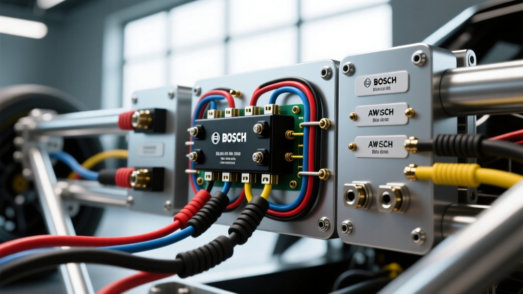
When transitioning a street vehicle into a dedicated track car, the factory under-hood fuse box is often the first electrical casualty. OEM power distribution modules are designed for cost-efficiency and moderate temperature ranges, not the extreme vibration, heat soak, and high-current spikes inherent in motorsport. A dedicated race car relay panel centralizes power distribution, isolates sensitive ECU triggers from high-amperage loads, and allows for rapid track-side troubleshooting. By moving away from brittle factory wiring and adopting a centralized, DIN-rail-mounted relay architecture, you ensure that critical systems like fuel pumps, cooling fans, and lighting arrays receive clean, uninterrupted voltage.
Architecting the Race Car Relay Panel: Core Components
Power Distribution: Bus Bars and DIN Rails
The foundation of any reliable race car relay panel is a robust mounting system and power distribution block. Avoid cheap plastic terminal strips; instead, utilize marine-grade tin-plated copper bus bars for main power distribution and standard 35mm DIN rails for mounting relays and fuses. Tin plating prevents galvanic corrosion, which is critical when using copper wiring in damp track environments. Mount the DIN rail to a 1/8-inch aluminum backing plate, which acts as both a structural chassis and a supplemental heat sink for high-draw solid-state relays.
Relay Selection: ISO Mini vs. Solid-State
For standard inductive loads like cooling fans and fuel pumps, the ubiquitous 5-pin Bosch-style ISO Mini relay remains the gold standard due to its replaceability and high surge tolerance. However, for sensitive electronics or high-vibration environments where mechanical contact bounce is a concern, solid-state relays (SSRs) are superior. According to Littelfuse automotive relay application guidelines, mechanical relays must be derated by at least 20% for continuous inductive loads due to inrush currents. If your fuel pump draws 18A continuously, a standard 30A mechanical relay is operating too close to its limit; upgrade to a 40A relay or an SSR to prevent contact welding.
Circuit Planning and AWG Wire Sizing Matrix
Proper wire sizing is non-negotiable. Undersized wires cause voltage drop, leading to weak fuel pump performance and dim lighting. The following matrix is based on SAE J1128 standards for low-tension primary automotive cable, assuming a maximum 12-foot run from the panel to the load and back to the chassis ground.
| Circuit | Load Type | Max Draw | Wire AWG | Fuse Size | Relay Type |
|---|---|---|---|---|---|
| Main Panel Feed | Constant 12V+ | 120A | 2 AWG | 150A ANL | N/A (Bus Bar) |
| Fuel Pump | Inductive | 18A | 10 AWG | 25A | 40A Bosch ISO |
| Cooling Fan | Inductive | 25A | 10 AWG | 35A | 40A Bosch ISO |
| Headlights (HID/LED) | Resistive/Capacitive | 10A | 12 AWG | 15A | 30A ISO Mini |
| ECU Main Power | Sensitive | 5A | 14 AWG | 10A | Solid-State (SSR) |
Step-by-Step Wiring and Assembly Protocol
Phase 1: Main Power and Chassis Grounding
Begin by routing 2 AWG battery cable from the master kill switch to the main positive bus bar on your panel. For the ground, do not rely on the engine block or suspension components. Run a dedicated 2 AWG ground cable from the negative bus bar directly to a cleaned, bare-metal point on the chassis firewall, secured with a heavy-duty copper ring terminal and a serrated flange nut. Paint and powder coating are insulators; you must use a wire wheel to expose bare steel or aluminum before bolting down the ground lug. Apply dielectric grease over the terminal after torquing to 15 ft-lbs to prevent oxidation.
Phase 2: Trigger Wiring and Flyback Diode Integration
When wiring the control side of the relay panel, understanding the standard 5-pin Bosch pinout is critical:
- Pin 30: 12V+ Constant Power (from fused bus bar)
- Pin 87: Switched Output (to the load)
- Pin 85: Coil Ground
- Pin 86: Coil Trigger (12V+ from dashboard switch or ECU)
- Pin 87a: Normally Closed (unused in most race applications; clip the pin to prevent shorts)
Critical Expert Tip: When switching inductive loads (like fuel pumps) via an ECU driver or a sensitive solid-state dashboard switch, the collapsing magnetic field of the relay coil generates a massive voltage spike (inductive kickback). This spike can instantly fry an ECU transistor. Always solder a 1N4001 flyback diode across the relay coil terminals (Pin 85 and Pin 86), with the diode stripe facing the 12V+ trigger source (Pin 86). This safely recirculates the voltage spike back into the coil.
Connector Selection: Deutsch DT vs. Weather-Pack
For a race car relay panel, the connectors you choose dictate the reliability of the entire harness. While Delphi Weather-Pack connectors are inexpensive and widely available, their open-cavity design makes them susceptible to moisture ingress and high-pressure power washing. For professional motorsport applications, standardize on Deutsch DT series connectors. The DT series utilizes a silicone rear grommet and an internal wedge lock that ensures the crimped contacts cannot back out under extreme vibration. Use 16-14 AWG size 16 contacts for trigger wires and 12-10 AWG size 12 contacts for power feeds. Always use dual-wall, adhesive-lined heat shrink over the back of the connector boots to create a watertight seal against the wire jacket.
Troubleshooting Track-Day Electrical Gremlins
Even meticulously built race car relay panels can develop issues after hours of track abuse. When troubleshooting, avoid the trap of simply checking for "12 volts" with a cheap test light. A test light draws minimal current and will illuminate even on a circuit suffering from severe strand corrosion or a loose crimp.
Instead, perform a voltage drop test under load. Set your multimeter to DC Volts. Place the red probe on the battery positive terminal and the black probe on the load side of the relay (Pin 87 output wire) while the circuit is active. A healthy circuit should show a voltage drop of less than 0.2V. If you read 1.5V or higher, you have high resistance in the power feed, the relay contacts are pitted, or the bus bar connection is loose.
Furthermore, ensure your panel layout complies with basic electromagnetic compatibility (EMC) principles. As outlined in SAE J1113 standards for automotive EMC, high-current switching wires (Pin 30 and 87) should never be bundled in the same loom as low-voltage sensor wires or ECU trigger wires (Pin 86). Keep high-amperage feeds separated from sensitive data lines by at least 4 inches to prevent inductive cross-talk, which can manifest as erratic datalogging or phantom misfires on the track.