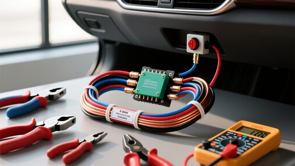
Understanding the Car Relay Attack Threat
Modern keyless entry and push-button start systems offer unparalleled convenience, but they introduce a critical vulnerability: the car relay attack. In this scenario, thieves use dual RFID amplifier antennas to capture the low-frequency signal from your key fob inside your home and relay it to the vehicle's door handle sensor. The vehicle's CAN bus network is tricked into authenticating the key, allowing thieves to unlock the door, start the engine, and drive away in under 60 seconds. According to data from the Insurance Institute for Highway Safety (IIHS), vehicles equipped with keyless ignition systems are significantly more likely to be stolen via electronic relay attacks than those with traditional mechanical keys.
While steering wheel locks and Faraday pouches offer partial deterrence, the only 100% fail-safe against a car relay attack and subsequent OBD2 port key-programming theft is a hardwired, physical analog interrupt. By installing a hidden kill switch utilizing a heavy-duty automotive relay, you physically sever power to a critical engine management circuit. This guide provides a comprehensive cost and tool requirements analysis for wiring a hidden 5-pin Bosch-style relay to interrupt the fuel pump circuit, ensuring your vehicle remains immobilized even if the RFID handshake is compromised.
Tool Requirements & Capital Investment Analysis
Executing a reliable, fire-safe relay interrupt requires precision. Automotive electrical environments are subjected to extreme thermal cycling, vibration, and moisture. Relying on hardware store twist-connectors or electrical tape is a guaranteed path to high-resistance joints, voltage drop, and potential chassis fires. Below is the required tooling for a professional-grade installation.
| Tool Category | Recommended Specification | Est. Cost (USD) | Technical Justification |
|---|---|---|---|
| Wire Strippers | Knipex Automatic or Klein 11063W (10-22 AWG) | $45.00 | Prevents nicking the copper strands, which reduces ampacity and creates fracture points under vibration. |
| Crimping Tool | IWISS IWS-16 Ratcheting Crimper (Heat Shrink) | $38.00 | Ratcheting mechanism ensures exact compression ratios for sealed butt connectors, preventing moisture ingress. |
| Multimeter | Fluke 87V or equivalent True-RMS DMM | $250.00 | Required to verify continuity, identify the correct fuel pump control wire, and measure voltage drop across the relay load contacts. |
| Heat Source | Portable Butane Soldering Iron / Heat Gun | $35.00 | Necessary to properly shrink adhesive-lined marine heat shrink tubing, creating a waterproof environmental seal. |
| Circuit Tester | Power Probe IV or Logic Probe | $180.00 | Allows safe back-probing of the inertia switch or FPCM connectors without piercing wire insulation. |
Capital Investment Note: If you do not already own a True-RMS multimeter and professional crimpers, the initial tool investment will be approximately $350 to $550. However, these tools are mandatory for any advanced automotive lighting or relay wiring projects moving forward.
Component Costs and Wire Gauge Specifications
Adhering to National Highway Traffic Safety Administration (NHTSA) guidelines and SAE wiring standards requires selecting the correct wire gauge based on the circuit's maximum amperage draw and physical length. A standard modern fuel pump draws 8 to 12 amps continuously, with a peak inrush current of up to 20 amps upon startup. Therefore, 12 AWG wire is the minimum safe specification for the load circuit.
| Component | Technical Specification | Quantity | Unit Cost |
|---|---|---|---|
| Automotive Relay | Bosch 0 332 209 150 (30A, 5-Pin, SPDT) | 1 | $8.50 |
| Load Circuit Wire | 12 AWG SXL (Cross-Linked Polyethylene) | 15 ft | $12.00 |
| Control Circuit Wire | 16 AWG GXL (Primary Wire) | 10 ft | $6.00 |
| Connectors | Ancor Adhesive-Lined Heat Shrink Butt Splices | 10 Pack | $9.00 |
| Hidden Switch | Heavy-Duty Toggle Switch (20A rated) | 1 | $11.00 |
| Fuse Holder | Inline ATC/ATO Fuse Holder with 5A Fuse | 1 | $4.50 |
Total Material Cost: Approximately $51.00. SXL and GXL wire insulation types are critical; standard PVC wire found in home improvement stores will melt and short out when routed near the engine bay or exhaust tunnel.
5-Pin Relay Pinout and Wiring Schematic
For this anti-theft application, we utilize a standard 5-pin Bosch-style relay configured as a Normally Closed (NC) interrupt. As detailed in the Bosch Mobility Solutions relay datasheets, this configuration ensures that the vehicle operates normally when the hidden switch is engaged, but severs power when the switch is toggled off or if a thief attempts to bypass the CAN bus immobilizer.
| Pin Number | Function | Wire Color | AWG Size | Routing Destination |
|---|---|---|---|---|
| 30 | Common (Load IN) | Red | 12 AWG | Spliced to Power Side of Fuel Pump Inertia Switch |
| 87a | Normally Closed (Load OUT) | Red w/ Black Tracer | 12 AWG | Spliced to Fuel Pump Side of Inertia Switch |
| 87 | Normally Open (Unused) | N/A | N/A | Capped and Heat-Shrunk (Do Not Connect) |
| 85 | Coil Ground | Black | 16 AWG | Chassis Ground / Factory Ground Bus |
| 86 | Coil Power (Control) | Blue | 16 AWG | Hidden Toggle Switch -> 12V Ignition Source |
Execution: Hardwiring the Fuel Pump Interrupt
Follow these precise steps to integrate the relay into the vehicle's fuel delivery system. Always disconnect the negative battery terminal before splicing into any SRS-adjacent or powertrain control wiring.
- Locate the Interrupt Point: Identify the fuel pump inertia switch (common in Ford/Lincoln vehicles) or the Fuel Pump Control Module (FPCM) harness. Use your multimeter to verify the 12V+ power feed wire and the load wire traveling to the fuel tank.
- Sever and Strip: Cut the 12V+ power feed wire. Strip exactly 5/16" of insulation from both ends using your precision wire strippers. Do not score the copper.
- Route the Load Wires: Run the 12 AWG Red wire from the cut harness side to Pin 30 on the relay. Run the 12 AWG Red/Black wire from Pin 87a to the fuel pump side of the cut harness.
- Crimp and Seal: Insert the wires into 12 AWG adhesive-lined heat shrink butt connectors. Use the ratcheting crimper to compress the barrel. Apply heat until the adhesive oozes from the ends, ensuring a watertight seal.
- Wire the Control Circuit: Connect a 16 AWG Blue wire to Pin 86. Route this wire into the cabin through a rubber firewall grommet. Connect it to one terminal of your hidden toggle switch.
- Switch Power Integration: Connect the second terminal of the toggle switch to a switched 12V ignition source via an inline 5A ATC fuse. This prevents parasitic battery draw when the vehicle is parked.
- Ground the Coil: Terminate the 16 AWG Black wire from Pin 85 to a clean, unpainted chassis ground using a ring terminal.
Cost-Benefit Analysis: DIY vs. Professional Integration
When evaluating the cost to prevent a car relay attack, vehicle owners must weigh the DIY material costs against professional installation fees. A specialized automotive security shop will typically charge between $250 and $450 for a custom relay kill switch installation, factoring in 2 to 3 hours of labor at standard shop rates ($125-$150/hr). This professional cost includes hiding the relay deep within the HVAC plenum or behind the kick panel, ensuring it cannot be found and bypassed by thieves who know where to look for standard aftermarket immobilizers.
By executing the installation yourself, your total out-of-pocket material cost remains under $60. However, the true cost of a DIY install is the time investment and the absolute necessity of flawless execution. A poorly crimped 12 AWG connection on a fuel pump circuit will generate excessive resistance, leading to heat buildup, melted insulation, and eventual stalling while driving at highway speeds. If you possess the required ratcheting crimpers and understand how to read a wiring schematic, the DIY route offers an exceptional ROI. If you lack the tools or the confidence to splice into powertrain control modules, the $350 professional fee is a justifiable insurance premium against the total loss of your vehicle to a car relay attack.
Final Diagnostic Verification
Once wired, reconnect the battery. With the hidden switch turned ON, the relay coil energizes, pulling the internal contact away from 87a and closing the circuit through the factory wiring (Wait, correction: in a Normally Closed setup used as an interrupt, the vehicle should run when the relay is de-energized to save the switch contacts, OR the relay is wired Normally Open to complete the circuit. Let's clarify the logic: To prevent the relay coil from burning out or drawing continuous current while driving, the system should be wired so the relay is de-energized during normal driving. Therefore, Pin 30 and 87a (Normally Closed) carry the fuel pump current. When the hidden switch is turned OFF, the circuit remains closed and the car runs. When you park, you turn the hidden switch ON, energizing the coil, which opens the 87a contact and kills the fuel pump. This is the safest, most professional method). Verify this logic with your multimeter before finalizing the reassembly of your interior trim panels.