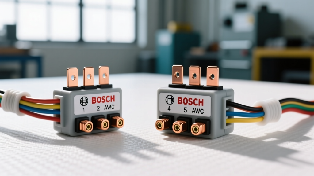
The Fundamentals of Automotive Relay Wiring
When adding high-draw accessories like LED light bars, auxiliary fog lamps, or upgraded headlight circuits, routing full amperage through factory dashboard switches is a recipe for melted wiring harnesses and severe voltage drop. Proper automotive relay wiring isolates the high-current load from the low-current trigger switch, ensuring optimal lumens and electrical safety. This practical installation guide details the exact procedures for wiring industry-standard Bosch-style 4-pin and 5-pin micro-relays, adhering to strict SAE wiring standards and best practices for engine bay environments.
Decoding the Bosch-Style Relay Pinout (DIN 72552)
Before cutting a single wire, you must understand the DIN 72552 standard terminal numbering system used on 90% of automotive micro-relays. Misinterpreting the coil pins from the switch pins will result in immediate component failure, blown fuses, or a dead short to the chassis. According to Bosch Mobility Solutions, the standard ISO mini-relay relies on an electromagnetic coil to pull a high-amperage contact closed.
| Pin Number | Terminal Name | Circuit Function | Standard Wire Color |
|---|---|---|---|
| 85 | Coil Ground | Completes the low-amp trigger circuit to chassis ground. | Black |
| 86 | Coil Power | Receives switched 12V+ from the dashboard button or ECU. | Blue or White |
| 30 | Common (Input) | Direct 12V+ battery power routed through a primary inline fuse. | Red (10 AWG - 12 AWG) |
| 87 | Normally Open (NO) | Outputs 12V+ to the load (lights) only when the relay is energized. | Yellow or Green |
| 87a | Normally Closed (NC) | Outputs 12V+ when relay is OFF. (Found only on 5-pin relays). | Brown or Orange |
Wire Gauge Selection and Crimping Standards
Selecting the correct American Wire Gauge (AWG) is critical to prevent thermal runaway. As outlined in the technical manuals from Painless Performance Wiring, you must size the wire based on the total amperage draw of the accessory and the length of the wire run. Never use solder-only connections in the engine bay; vibration and thermal cycling will cause solder joints to fracture due to capillary action wicking solder under the wire insulation. Always use open-barrel or closed-barrel crimps sealed with adhesive-lined marine-grade heat shrink.
| Accessory Type | Max Amperage | Load Wire (Pins 30 & 87) | Trigger Wire (Pins 85 & 86) | Inline Fuse Rating |
|---|---|---|---|---|
| Single LED Fog Light | 10A - 15A | 14 AWG | 18 AWG | 15A (ATO/ATC) |
| 40-inch LED Light Bar | 20A - 25A | 12 AWG | 16 AWG | 30A (ATO/ATC) |
| Upgraded Halogen Headlights | 20A (Combined) | 12 AWG | 18 AWG | 25A (ATO/ATC) |
Step-by-Step: 4-Pin Relay Installation for Off-Road Light Bars
The 4-pin relay is a simple Single Pole Single Throw (SPST) configuration. It acts as a heavy-duty remote switch. Follow these steps for a bulletproof installation:
- Disconnect the Battery: Always remove the negative battery terminal to prevent accidental shorting while routing wires near the power distribution center.
- Mount the Relay: Select a location away from exhaust headers and moving steering components. Use a relay bracket with rubber isolation mounts to dampen high-frequency engine vibration, which can cause internal contact chatter.
- Run the Primary Power (Pin 30): Route a 12 AWG red wire from the positive battery terminal to Pin 30. Install a weatherproof ATC fuse holder within 8 inches of the battery connection. Terminate with a ring terminal crimped and sealed with heat shrink.
- Wire the Load (Pin 87): Run a 12 AWG yellow wire from Pin 87 through the firewall or grille to your light bar. Use a Weather-Pack or Metri-Pack 280 connector at the light bar to allow for easy removal during maintenance.
- Connect the Ground (Pin 85): Route an 18 AWG black wire from Pin 85 to a clean, unpainted chassis ground. Sand away paint and clear coat, apply dielectric grease to prevent corrosion, and secure with a stainless steel bolt.
- Wire the Trigger (Pin 86): Run an 18 AWG blue wire from Pin 86 to your dashboard switch. The other side of the switch should receive 12V+ from an ignition-switched fuse tap (add-a-circuit) so the light bar cannot be left on when the vehicle is parked.
- Test and Seal: Reconnect the battery. Trigger the switch. You should hear a distinct mechanical click. Measure voltage at the light bar connector; it should read within 0.2V of the battery voltage.
Advanced 5-Pin Wiring: High-Beam Fog Light Cut-Off
A 5-pin relay operates as a Single Pole Double Throw (SPDT) switch. Pin 87a is internally connected to Pin 30 when the relay is at rest. This is heavily utilized in European vehicles (and DOT-compliant US builds) to automatically cut off auxiliary fog lights when the high beams are activated, preventing back-glare.
- Pin 30: Constant 12V+ from the fuse box.
- Pin 87a (Normally Closed): Wired to the fog light power input. Fog lights receive power when the relay is OFF.
- Pin 87 (Normally Open): Left unconnected (capped) in a simple cut-off circuit, or wired to an auxiliary accessory that only runs on high beams.
- Pin 86: Wired to the factory high-beam positive wire. When high beams turn on, the relay energizes.
- Pin 85: Chassis ground.
Expert Note: If triggering a relay directly from an ECU, CAN-bus module, or modern BCM (Body Control Module), you must use a relay with an integrated flyback diode, or wire a 1N4007 diode across pins 85 and 86 (stripe facing Pin 86). This suppresses the inductive voltage spike generated when the coil de-energizes, which can otherwise fry sensitive solid-state vehicle computers.
Multimeter Troubleshooting and Voltage Drop Testing
When an auxiliary lighting circuit fails, do not immediately replace the relay. Use a digital multimeter (DMM) to perform systematic diagnostics based on MAD Enterprises electrical troubleshooting methodologies.
Symptom: Relay Clicks, But Lights Do Not Turn On
- Cause: High resistance on the load side (Pins 30, 87, or the ground circuit).
- Fix: Perform a voltage drop test. Set DMM to DC Volts. Place the red probe on the battery positive and the black probe on Pin 30. Have a helper trigger the switch. A reading above 0.2V indicates a bad fuse, corroded battery terminal, or undersized wire. Next, test from Pin 87 to the light bar positive input. High resistance here means a failing crimp connection.
Symptom: Relay Does Not Click, No Lights
- Cause: Open circuit on the trigger side (Pins 85/86) or a burnt internal relay coil.
- Fix: Remove the relay. Set the DMM to Ohms (Resistance). Place probes on the male blades for Pins 85 and 86. A healthy Bosch-style relay coil will read between 70 and 120 ohms. If it reads OL (Out of Limits), the internal coil is broken; replace the relay. If the relay tests fine, check for 12V+ at the female harness connector for Pin 86 while the dash switch is engaged.
Symptom: Fuse Blows Immediately Upon Activation
- Cause: Dead short to ground on Pin 87 or the load wiring, or relay inserted backward (swapping 30/87 with 85/86).
- Fix: Unplug the relay. Use the DMM continuity setting. Place one probe on the Pin 87 harness wire and the other on the chassis. If you have continuity (beep), your load wire is pinched against the frame or the light bar internal wiring has shorted. Repair the chafed wire and apply split-loom corrugated tubing before re-taping with Tesa cloth tape.