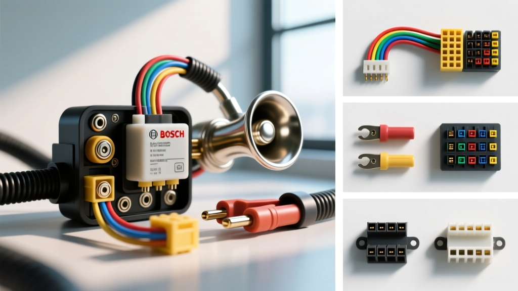
Why Factory Horn Circuits Fail with Upgrades
Upgrading from a weak factory snail horn to dual Fiamm Freeway Blasters, Hella Supertones, or a full air horn system is a common modification for automotive enthusiasts. However, factory horn circuits are typically wired with thin 18 AWG wire and protected by a 10A fuse, routed directly through the steering column clock spring and horn button contacts. When you connect high-amperage aftermarket horns directly to this circuit, the excessive current draw will melt the clock spring rotary connector and fry the factory horn button. The solution is a dedicated relay circuit. This guide compares the best wiring kits and details exactly how to wire a car horn relay using proper automotive connectors, wire gauges, and crimping techniques.
Understanding Horn Relay Types: ISO 7588 Standard
The automotive industry relies heavily on the ISO 7588 standard, commonly referred to as the 'Bosch-style' relay. For horn applications, you will encounter two primary variants:
- 4-Pin Mini/Micro Relays (SPST): Features pins 30, 87, 85, and 86. This Single Pole Single Throw (Normally Open) relay is the standard for 95% of electric horn upgrades. It acts as a simple on/off switch triggered by the factory horn button.
- 5-Pin Relays (SPDT): Adds pin 87a (Normally Closed). While commonly found in automotive parts stores, the 87a pin is entirely unnecessary for standard horn wiring and is simply left unconnected. Using a 5-pin relay in a 4-pin socket is perfectly safe, provided the socket lacks a receptacle for 87a.
For high-amperage air horn compressors (like Viair 480C) that pull over 30A continuously, a standard 30A/40A Bosch relay may overheat. In these cases, a heavy-duty continuous-duty starter solenoid (rated for 85A+) is required instead.
Product Comparison: Selecting the Right Horn Wiring Kit
When learning how to wire a car horn relay, selecting the right harness is critical. Pre-wired kits save time, while DIY pigtails offer custom routing. Below is a comparison of the three main kit types available on the market.
| Kit Type | Relay Type | Wire Gauge | Connectors | Best Application |
|---|---|---|---|---|
| OEM-Style Pre-Wired (e.g., Hella, PIAA) | 4-Pin Bosch w/ Bracket | 12 AWG TXL | Molded Weatherpack, Ring Terminals | Plug-and-play dual electric horns (Hella Supertones, Fiamm). |
| Universal Relay Pigtail (DIY) | 4-Pin Standard Socket | N/A (Requires bulk wire) | Raw 1/4 inch Spades | Custom air horn setups, tight engine bays requiring exact wire lengths. |
| Heavy-Duty Solenoid Harness (e.g., Painless) | Continuous-Duty Solenoid | 8 AWG to 10 AWG | Heavy-Duty Ring Terminals, Mega Fuses | Train horns, Viair compressors, high-amperage off-road accessories. |
Selection Verdict: For standard dual electric horns pulling 15A-20A, a high-quality pre-wired 12 AWG harness with an integrated inline ATC fuse holder is the most reliable choice. It eliminates the need to crimp heavy-gauge power wires and provides weather-sealed connections.
How to Wire a Car Horn Relay: Step-by-Step Guide
If you opt for a DIY pigtail approach or need to repair a damaged factory harness, follow this professional-grade installation procedure.
Step 1: Wire Gauge and Fuse Selection
According to SAE J1128 standards for low-tension primary cable, wire gauge must be selected based on the maximum amperage draw and the length of the wire run. Always use GXL or TXL cross-linked polyethylene wire, which offers high-temperature resistance and a thin wall for easier routing through the firewall or grille.
| Horn Type | Typical Amperage | Recommended Wire Gauge | Inline Fuse Rating (ATC/ATO) |
|---|---|---|---|
| Single OEM Replacement | 5A - 8A | 16 AWG | 10A |
| Dual Electric (e.g., Fiamm, Hella) | 12A - 20A | 12 AWG | 20A |
| Compact Air Compressor | 20A - 30A | 10 AWG | 30A |
Step 2: Pinout Identification and Routing
The standard ISO 7588 4-pin relay pinout is stamped directly onto the relay casing. Here is how to route each circuit:
- Pin 30 (Common / Power In): Connect directly to the battery positive terminal using 12 AWG wire. Crucial: Install an inline ATC fuse holder within 6 inches of the battery terminal to protect the entire harness in the event of a short.
- Pin 87 (Normally Open / Power Out): Connect to the positive terminal(s) of your aftermarket horn(s) using 12 AWG wire.
- Pin 85 (Coil Trigger): Tap into the factory horn trigger wire. This wire only carries a low-amperage signal (under 2A) to activate the relay coil. Use 16 AWG wire for this connection.
- Pin 86 (Coil Ground): Connect to a clean, bare-metal chassis ground point using 16 AWG wire and a ring terminal secured with a star washer to bite through paint and prevent ground loop issues.
Technical Note: On standard non-diode relays, pins 85 and 86 are interchangeable. However, if you are using a relay with an internal suppression diode (marked with a polarity symbol on the casing), Pin 86 must be Ground and Pin 85 must be the 12V Trigger to prevent blowing the factory horn fuse.
Step 3: Professional Crimping and Connector Selection
The most common cause of horn failure is poor terminal crimping leading to voltage drop and arcing. Never use standard pliers to crimp automotive terminals.
- Relay Socket Terminals: Use 1/4 inch (6.3mm) fully insulated nylon female quick-disconnect spades. For pins 30 and 87 (Power), use 12-10 AWG rated terminals. For pins 85 and 86 (Trigger/Ground), use 16-14 AWG terminals.
- Crimping Tool: Use a ratcheting crimper (such as the IWISS SN-48B or equivalent). A ratcheting tool ensures a gas-tight crimp on the copper wire barrel while simultaneously folding the insulation grip securely over the wire jacket. This prevents the wire from pulling out under engine bay vibration.
- Splicing the Trigger Wire: Do not use cheap vinyl crimp caps or T-taps to connect to the factory horn switch wire. These invite galvanic corrosion and moisture intrusion. Instead, use solder-seal heat shrink butt connectors (e.g., 3M Scotchlok). When heated, the internal solder ring melts to fuse the copper strands, while the outer polyolefin tubing shrinks and extrudes adhesive to create a completely waterproof seal.
Troubleshooting Common Horn Relay Failures
If your newly wired horn system is malfunctioning, use this diagnostic decision tree:
- Symptom: Horn clicks but does not sound.
Cause: The relay coil is energizing (clicking), but there is a voltage drop on the high-current circuit (Pins 30 or 87).
Fix: Perform a voltage drop test across the fuse holder, the relay pins, and the horn ground. Check for undersized wire or a loose 1/4 inch spade terminal that has lost tension. - Symptom: Horn works when engine is off, but sounds weak or fails when engine is running.
Cause: Alternator interference or a poor chassis ground on Pin 86 causing the coil to receive fluctuating voltage.
Fix: Relocate the Pin 86 ground to the battery negative terminal or a dedicated grounding bus bar. Ensure the ground ring terminal is sanded down to bare metal. - Symptom: Horn stays on continuously.
Cause: The relay contacts (Pins 30 and 87) have welded together internally due to extreme arcing from an inductive load without a flyback diode, or the factory horn button is shorted.
Fix: Replace the relay. If the issue persists, check the factory clock spring and steering wheel horn pad for a physical short to ground.
Authoritative References
For further reading on automotive electrical standards and relay specifications, consult the following resources:
- SAE J1128: Low Tension Primary Cable Standard - Guidelines for selecting proper automotive wire gauges and insulation types.
- SAE J284: Relays for Automotive Applications - Engineering standards for ISO 7588 Bosch-style relay testing and pinout configurations.
- Painless Performance Wiring Manuals - Industry-standard reference for routing, fusing, and crimping high-amperage automotive accessory circuits.