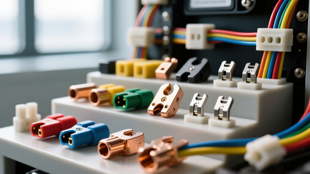
Mastering Automotive Wire Splice Connector Types
The modern automotive electrical system is a hostile environment for wiring repairs. Between engine bay thermal cycling (ranging from -40°F to over 250°F), constant high-frequency vibration, and exposure to road salts and moisture, a poorly executed wire splice will inevitably fail. When diagnosing parasitic draws, intermittent sensor codes, or voltage drops, the root cause is frequently traced back to inferior splicing methods. Understanding the specific wire splice connector types available to automotive technicians is the first step toward achieving OEM-level harness reliability.
Unlike household wiring, automotive circuits rely on flexible, multi-strand copper wire that is highly susceptible to capillary action—a phenomenon where moisture wicks beneath the wire insulation and corrodes the copper strands from the inside out. To combat this, professional technicians must select the correct connector metallurgy, insulation material, and installation technique. This guide breaks down the industry-standard wire splice connector types and provides a masterclass installation procedure.
Comprehensive Breakdown of Wire Splice Connector Types
1. Adhesive-Lined Heat Shrink Butt Connectors (The Gold Standard)
For 90% of automotive harness repairs, dual-wall, adhesive-lined heat shrink butt connectors are the undisputed gold standard. These connectors feature a copper or tinned-brass barrel for the mechanical and electrical connection, encased in a polyolefin outer tubing. The critical differentiator is the inner layer of thermoplastic adhesive. When heated to approximately 120°C (250°F), the polyolefin shrinks by 50%, while the inner adhesive melts at around 85°C (185°F), flowing into the wire strands and creating a hermetic, waterproof seal. This completely halts capillary wicking and prevents oxidation.
2. Solder Seal Splice Connectors
Solder seal connectors utilize a transparent heat shrink tube with an integrated ring of low-temperature solder and flux. When heated, the solder melts and flows around the stripped wire strands, while the outer tubing shrinks to form a seal. While these provide excellent electrical conductivity and are great for tight spaces in dashboard harnesses, they are generally not recommended for high-vibration areas like engine bays or suspension-mounted ABS sensors. Solder creates a rigid point on a flexible stranded wire, which can lead to stress fractures and wire breakage just outside the splice joint under constant vibration.
3. Nylon and Vinyl Insulated Crimp Splices
These are the traditional, non-heat-shrink crimp connectors featuring a metal barrel wrapped in a molded nylon or vinyl sleeve. While they are fast to install and highly effective in dry, climate-controlled cabin environments (such as behind the radio or under the dash), they offer zero moisture protection. Using these in an engine bay or exterior lighting harness is a critical failure point, as moisture will easily penetrate the sleeve and corrode the bare copper.
4. Mechanical Gel-Cap and Inline Splice Connectors
Often used in telecommunications, some automotive technicians utilize mechanical inline connectors filled with dielectric silicone gel. While the gel displaces moisture, these connectors are bulky, difficult to wrap in automotive friction tape, and do not meet SAE J1128 standards for under-hood harness flexibility. They should be avoided in favor of proper heat-shrink crimps.
Automotive Wire Gauge (AWG) to Connector Color Matrix
Matching the connector barrel size to the wire gauge is non-negotiable. A loose crimp will cause arcing and voltage drop; a crimp that is too tight will sever the copper strands. Refer to this standard automotive color-coding matrix before selecting your wire splice connector types:
| Connector Color | AWG Range | Metric (mm²) | Typical Automotive Application |
|---|---|---|---|
| Red | 22 - 18 AWG | 0.5 - 0.8 mm² | Sensor signals, CAN bus lines, tail lights (e.g., 18 AWG Brown wire) |
| Blue | 16 - 14 AWG | 1.0 - 2.0 mm² | Fuel injectors, interior lighting, horn relays, 12V accessory feeds |
| Yellow | 12 - 10 AWG | 3.0 - 5.0 mm² | Headlight power feeds, starter solenoid triggers, high-amperage grounds |
Step-by-Step Installation: Adhesive Heat Shrink Butt Splice
To achieve a factory-grade repair, follow this precise installation methodology. For this example, we are repairing a damaged 16 AWG Black ground wire on a tail light harness.
Step 1: Precision Wire Stripping
Use a calibrated, self-adjusting wire stripper. Strip exactly 1/4 inch (6mm) to 5/16 inch (8mm) of insulation from both wire ends. Do not score or nick the outer copper strands; even a microscopic nick will create a stress point that will snap under thermal expansion. Ensure the strands remain tightly twisted in their original lay direction.
Step 2: Barrel Insertion and Verification
Insert the stripped wire into the metal barrel of the butt connector. The wire should be visible just past the end of the metal barrel, but no bare copper should be exposed outside the connector. If the wire slides in with zero resistance, the connector is too large. If you have to force it, the connector is too small.
Step 3: The Ratcheting Crimp Technique
Never use standard slip-joint pliers or side-cutters to crimp. Use a dedicated ratcheting crimping tool designed for insulated terminals (such as the Titan 11904 or Knipex Twin Ferrule). Place the metal barrel in the correct die size (Blue for 16-14 AWG). Squeeze the handles until the ratchet releases. This ensures a uniform, gas-tight cold weld that deforms the copper and barrel into a single solid mass, eliminating air pockets where oxidation could start.
Step 4: The Pull Test
Before applying heat, grip the wire on both sides of the splice and pull firmly. A proper gas-tight crimp will withstand over 30 lbs of tensile force. If the wire pulls out of the barrel, the crimp failed; cut it off and start over with a new connector.
Step 5: Controlled Heat Shrinking
Use a heat gun set to approximately 250°F (120°C) or a specialized butane soldering iron with a hot-air attachment. Never use an open-flame lighter, as it will scorch the polyolefin and destroy the adhesive properties. Start heating in the center of the metal barrel and slowly work your way outward toward the wire insulation. You will know the seal is complete when a small bead of melted adhesive extrudes from both ends of the tubing, completely encapsulating the wire jacket.
The Solder vs. Crimp Debate: What Industry Standards Dictate
A common misconception among DIYers is that soldering a wire splice is superior to crimping. In the automotive sector, this is categorically false. According to guidelines referenced by the AutoShop 101 electrical training modules and IPC/WHMA-A-620 standards for cable assemblies, solder-only splices are prohibited in high-vibration environments. Solder wicks up into the stranded wire via capillary action, creating a stiff, brittle transition zone between the flexible wire and the rigid solder joint. Engine vibration will quickly cause the wire to fatigue and snap at this exact transition point. A properly executed mechanical crimp maintains the flexibility of the wire while providing superior tensile strength and lower electrical resistance.
Diagnostic Troubleshooting: Splice Failure Modes
Even with the correct wire splice connector types, errors in execution can lead to elusive electrical gremlins. Here is how to diagnose common splice failures:
- Voltage Drop Across the Splice: Set your multimeter to DC Volts. Place the red probe on the wire leading into the splice and the black probe on the wire exiting the splice. With the circuit under load (e.g., headlights turned on), a healthy splice should show less than 0.1V drop. A reading higher than 0.2V indicates a loose crimp or internal corrosion.
- Capillary Wicking and Green Crust: If you see green copper oxide (verdigris) forming on the wire strands inches away from the splice, the heat shrink seal failed. Moisture entered the joint and wicked down the wire. The only fix is to cut back the wire until you reach clean, shiny copper, and re-splice.
- Thermal Melting: If the polyolefin tubing is melted or scorched, excessive resistance in the crimp barrel is generating heat. This is almost always caused by using a connector rated for a smaller AWG wire than what was installed, or failing to use a ratcheting crimper.
Expert Tips for OEM-Level Harness Repairs
When repairing complex harnesses, such as those containing CAN bus networks or high-speed sensor data lines, maintaining the physical geometry of the wire is just as important as the electrical connection. Twisted pair wires (like CAN High and CAN Low) must retain their twist rate right up to the splice point to maintain impedance and prevent signal reflection. Furthermore, always wrap your completed splices in Tesa 51036 PET cloth friction tape or high-quality 3M Super 33+ vinyl tape to match the OEM harness wrapping. This prevents the splice from rattling against the chassis and protects it from abrasion. For comprehensive vehicle-specific wiring diagrams and pinout configurations to verify your repair points, always consult the factory service manual or established databases like Mouser's automotive wiring application guides to ensure your wire color codes and AWG sizes match the manufacturer's original specifications.