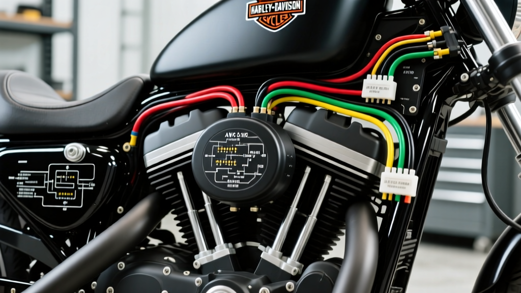
When stripping down a Harley-Davidson for a bobber, chopper, or cafe racer build, the factory wiring harness is often the first casualty. Modern factory harnesses are bloated with CAN-bus networks, emissions sensors, and diagnostic modules. For builders and restorers working with pre-2007 Evo and Twin Cam platforms, finding simple Harley wiring diagrams is critical to creating a reliable, minimalist electrical system. This technical specification reference breaks down the core circuits of the iconic Harley-Davidson Sportster (1991-2003 XL series) and Evo Big Twins, providing exact AWG ratings, pin configurations, and SAE-compliant wire specifications.
The Anatomy of a Simplified Harley Harness
A truly simplified Harley harness eliminates the Bank Angle Sensor (BAS), diagnostic data link connectors, and complex turn signal modules, relying instead on direct-switched circuits and solid-state components. The core electrical system is divided into three isolated but interacting subsystems: the Ignition Control Module (ICM) circuit, the 3-phase charging system, and the essential lighting/switchgear network. According to SAE J1128 standards, all low-tension primary cables used in these simplified diagrams must utilize cross-linked polyethylene (GXL or TXL) insulation to withstand engine bay temperatures exceeding 125°C (257°F) without melting or shorting.
Core Circuit 1: Ignition Control Module (ICM) Pinout
For pre-2004 Sportsters and many Evo Big Twins, the heart of the ignition system is the 8-pin Ignition Control Module. When referencing simple Harley wiring diagrams, the ICM is often the most misunderstood component. The module relies on a magnetic crankshaft position sensor (CKP) to determine timing. Below is the exact factory pinout required to wire a standalone ignition harness.
| Pin | Wire Color | AWG | Function & Routing |
|---|---|---|---|
| 1 | BK (Black) | 18 | Module Ground. Must route directly to battery negative or engine case star ground. |
| 2 | R/W (Red/White) | 16 | Switched 12V Power. Routes from ignition switch. Requires inline 10A fuse. |
| 3 | G (Green) | 18 | Tachometer Signal Output. Square wave output for aftermarket tachometers. |
| 4 | V (Violet) | 18 | MAP Sensor Reference (if applicable). Often capped in simplified custom builds. |
| 5 | BK/W (Black/White) | 18 | Front Coil Trigger. Low-side switch for the front cylinder ignition coil. |
| 6 | BK/Y (Black/Yellow) | 18 | Rear Coil Trigger. Low-side switch for the rear cylinder ignition coil. |
| 7 | G/R (Green/Red) | 18 | CKP Sensor Signal (+). Shielded cable required to prevent EMI from spark plug wires. |
| 8 | BK (Black) | 18 | CKP Sensor Ground (-). Dedicated ground back to Pin 1; do not share with lighting grounds. |
Expert Note: The most common failure mode in simplified ICM harnesses is Electromagnetic Interference (EMI) corrupting the CKP sensor signal. Always route the Green/Red and Black wires (Pins 7 and 8) as a twisted pair, and keep them at least 2 inches away from the high-tension spark plug leads and the stator output wires.
Core Circuit 2: Stator and Voltage Regulator Specifications
The charging system on a Harley-Davidson is a high-output, 3-phase alternator. Simplified diagrams often gloss over the critical wire gauges required to prevent voltage drop and connector melting. The stator outputs raw AC voltage, which is rectified and regulated to 14.2V–14.8V DC.
Stator to Regulator Routing
The stator utilizes three Yellow wires. These must be 12 AWG (minimum) to handle the 35-45 amp AC output without excessive resistance. The factory Molex connector is a known failure point due to thermal cycling and moisture ingress. In a simplified, high-reliability build, eliminate the plastic connector entirely. Instead, hard-solder the stator wires directly to the regulator pigtail and seal the joint with adhesive-lined, dual-wall heat shrink.
Regulator to Battery Routing
The voltage regulator requires robust DC output wiring. Use 10 AWG GXL wire for the positive (Red) and negative (Black) leads routing from the regulator to the battery. As detailed in Electrosport Industries' technical testing guidelines, voltage drop across the charging circuit must not exceed 0.2V at 3,000 RPM. If the regulator is chassis-grounded (floating ground design), the mounting surface must be bare metal, free of powder coat or paint, and secured with star washers to ensure a resistance of less than 0.05 ohms to the battery negative terminal.
Core Circuit 3: Essential Lighting and Switchgear
When building a minimalist harness, lighting circuits are stripped of complex flasher relays in favor of solid-state, load-independent LED flashers. Below is the standard specification for a simplified H4 headlight and basic switchgear setup.
- Headlight High Beam: White/Yellow (W/Y), 14 AWG. Max draw 60W (5A).
- Headlight Low Beam: Red/Yellow (R/Y), 14 AWG. Max draw 55W (4.5A).
- Headlight Ground: Black (BK), 14 AWG. Dedicated ground to the frame.
- Tail/Brake Light: Brown (Br) for running light, Yellow (Y) for brake. 16 AWG.
- Horn: Gray (Gy), 14 AWG. Requires a 15A inline fuse and a dedicated 30A relay if using a high-draw Stebel air horn.
Handlebar Switchgear and Control Routing
In a simplified setup, the complex multi-pin factory handlebar connectors are replaced with direct wire routing through the handlebars (if using internal wiring) or a streamlined external loom. The right-hand control typically houses the Run/Off switch and the starter button. The Run/Off switch must be wired in series with the ICM power feed (Pin 2). The starter button requires a heavy-duty 14 AWG feed to trigger the starter solenoid relay. Never route the starter button wire directly to the solenoid without a relay; the high inrush current (often exceeding 25A) will melt the internal contacts of the handlebar switch. Use a standard 4-pin Bosch-style ISO mini relay: Pin 86 to the starter button, Pin 85 to ground, Pin 30 to fused battery positive (10 AWG), and Pin 87 to the starter solenoid trigger terminal.
Connector and Terminal Standards
A simple wiring diagram is only as reliable as its terminations. Crimping and connector selection dictate the long-term viability of the harness. Avoid vinyl-insulated crimp terminals; they melt under engine heat and fail under vibration.
| Component | Recommended Terminal | Tooling Requirement |
|---|---|---|
| Ignition Coils | Push-on receptacle (18-16 AWG) | Ratcheting open-barrel crimper |
| Stator/Regulator | Hard-solder + Dual-wall heat shrink | Temperature-controlled soldering station |
| Ground Rings | Non-insulated ring terminal (12-10 AWG) | Hex-die ratcheting crimper |
| Sensors/Switches | Deutsch DT or Metri-Pack 150 series | Manufacturer-specific pin crimper |
Grounding Strategy: Star vs. Daisy Chain
The most critical element missing from generic simple Harley wiring diagrams is a proper grounding topology. Daisy-chaining grounds (connecting the tail light ground to the turn signal ground, then to the frame) creates varying ground potentials. When the brake light activates, the voltage drop on the shared ground wire can back-feed into the turn signals, causing erratic flashing or blown bulbs.
Implement a Star Grounding System. Create a single, massive ground stud (typically 5/16-18 or 3/8-16 thread) welded or bolted directly to the engine block or frame neck. Route every individual component ground (ignition, lighting, horn, regulator) directly to this single stud using its own dedicated wire. This ensures that high-current spikes from the horn or starter do not modulate the ground reference for sensitive electronics like the ICM or voltage regulator.
Summary of Wire Sizing and Fusing
To finalize your simplified harness, adhere to these maximum fuse ratings based on 14 AWG and 16 AWG GXL wire capacities in high-temperature motorcycle environments:
- Main Battery Feed (10 AWG): 30A Master Fuse (MAXI or ANL style).
- Ignition Circuit (16 AWG): 10A ATO Blade Fuse.
- Lighting Circuit (14 AWG): 15A ATO Blade Fuse.
- Horn/Accessories (14 AWG): 15A ATO Blade Fuse.
By adhering to these technical specifications, builders can translate simple Harley wiring diagrams into a robust, race-ready, or show-quality electrical system that withstands the intense vibration and thermal loads inherent to V-Twin motorcycles.