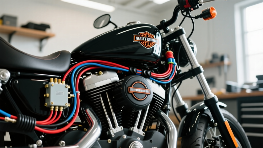
The Danger of Oversimplification in Custom Harley Harnesses
When builders search for a simple Harley wiring diagram, they are usually looking to strip away the complexity of modern CAN-bus systems, ABS modules, and security fobs to create a bare-bones bobber, chopper, or cafe racer. However, "simple" does not mean "forgiving." Motorcycle electrical systems operate in a high-vibration, high-heat, and high-moisture environment. A simplified schematic often omits critical circuit protection, relay logic, and precise AWG (American Wire Gauge) requirements. Following a basic diagram without understanding the underlying electrical physics is the leading cause of stator burnouts, melted main harnesses, and catastrophic lithium battery thermal events.
Critical Safety Warnings Before You Crimp
1. The Stator "Yellow Wire" Meltdown Hazard
The 3-phase AC stator on a Harley-Davidson Twin Cam, Evolution, or Milwaukee-Eight engine generates massive current—often exceeding 45 amps at highway RPMs. A common mistake when referencing a simple Harley wiring diagram is routing the three Yellow stator wires directly to the regulator/rectifier using standard 14 AWG wire and cheap bullet connectors.
The Safety Fix: You must use a minimum of 12 AWG (preferably 10 AWG) high-strand-count copper wire for the stator run. Solder and seal all connections using dual-wall, adhesive-lined heat shrink. According to SAE J1128 standards for low-tension primary cables, under-hood (or in this case, near-engine) wiring must withstand extreme thermal cycles. Standard PVC electrical tape will melt off the stator cover; use Tesa 51036 PET cloth tape or corrugated split loom for abrasion resistance.
2. Frame Grounding vs. Dedicated Ground Straps
Many simplified diagrams instruct you to "ground to frame." On modern rubber-mounted Harley-Davidson frames (Softail, Dyna, and Touring models post-2000), the engine and transmission are isolated from the frame by polyurethane bushings. Relying on the engine mounts for a ground path will force return current through the starter motor bearings or transmission main shaft, leading to rapid galvanic corrosion and catastrophic bearing failure.
The Safety Fix: Always run a dedicated 4 AWG or 2 AWG flexible braided copper ground strap directly from the battery negative terminal to the starter motor mounting bolt or a dedicated transmission ground lug. Torque the battery terminal bolts to 96–120 in-lbs and apply a dielectric grease (like NO-OX-ID A-Special) to prevent sulfate creep.
Top 5 Mistakes When Following a Simple Harley Wiring Diagram
Mistake 1: Undersizing the Main Power Feed
A basic diagram might show a single 12 AWG wire running from the battery to a 30A main fuse block. While 12 AWG is technically rated for 30A in free air, voltage drop over a 7-foot run to the rear of a Softail frame will starve the ignition coils of voltage. The Delphi MEFI (Multi-Port Electronic Fuel Injection) ECM requires a minimum of 11.5V to maintain proper injector pulse width.
The Fix: Use 8 AWG wire for the main battery feed to a rear-mounted fuse block, then step down to 14 AWG or 16 AWG for individual branch circuits. Use marine-grade tinned copper (UL 1426) to resist corrosion inside the frame tubes.
Mistake 2: Bypassing Relays for High-Draw Lighting
Connecting a 55W halogen headlight or high-draw LED auxiliary lamps directly to the ignition switch's "ACC" or "IGN" terminal will melt the Harley ignition switch contacts. The OEM switch is only designed to carry low-amperage signal current.
The Fix: Use the ignition switch to trigger a 30A automotive relay (standard Bosch-style 5-pin relay). Wire the high-current headlight circuit directly from the battery, through a dedicated fuse, into the relay's common (Pin 30) and normally open (Pin 87) terminals.
Mistake 3: Incorrect Deutsch Pin Crimping on Coil Packs
When wiring dual-fire or single-fire ignition coils, builders often use generic spade connectors that vibrate loose. Harley-Davidson uses Deutsch DT series connectors for the ignition coils and injectors due to their silicone secondary seals.
The Fix: Use the correct Deutsch DT04-4P (receptacle) and DT06-4S (plug) housings. You must use a specialized Deutsch crimp tool (like the TE Connectivity 58526-1) to crimp the solid wire barrel and the insulation support barrel simultaneously. A poorly crimped pin will back out of the housing under engine vibration, causing a dead cylinder and unburnt fuel to wash the cylinder walls. Refer to TE Connectivity's Deutsch DT specifications for proper cavity plug insertion and crimp depth.
Mistake 4: Ignoring the BCM on 2014+ Touring Models
If you are modifying a 2014 or newer Touring or Softail model, a simple Harley wiring diagram found on forums will likely ignore the Body Control Module (BCM). The BCM controls lighting, turn signal cancellation, and security. Splicing directly into the BCM outputs without using OEM-compatible LED load equalizers or CAN-bus decoders will throw U-codes (e.g., U1016 - Lost Communication with ECM) and put the BCM into a protective limp mode, killing your headlights and fuel pump.
The Fix: If retaining the BCM, use plug-and-play CAN-bus load equalizers. If completely deleting the BCM, you must source a standalone ignition module (like a Dyna S or a programmable Mule Engineering CAN-bus eliminator) to handle the digital handshake required by the ECM.
Mistake 5: Using Solid Core or Household Wire
Never use solid-core wire (like household Romex) or cheap hardware store stranded wire on a motorcycle. The engine harmonics and frame flex will cause solid copper to work-harden and snap within 500 miles.
The Fix: Always use fine-strand, multi-conductor automotive wire (GXL or TXL cross-linked polyethylene insulation) which is rated for 125°C continuous operation and highly resistant to vibration fatigue and petroleum-based fluids.
Harley-Davidson Simplified Circuit Protection & Wire Gauge Matrix
Use this reference chart to ensure your custom harness meets OEM safety tolerances. Wire colors reflect standard Harley-Davidson OEM coding.
| Circuit Function | OEM Wire Color | Min AWG Size | Max Fuse Rating | Connector Type |
|---|---|---|---|---|
| Main Battery Feed | Red | 8 AWG | 30A (Mega Fuse) | Ring Terminal (3/8") |
| Stator 3-Phase AC | Yellow (x3) | 12 AWG | None (Self-Protecting) | Metri-Pack 280 |
| Ignition Switch Feed | Red/White | 12 AWG | 15A | Molex MX150 |
| ECM / Fuel Injection | Orange (Switched) | 14 AWG | 10A | Delphi 32-Way |
| Headlight (High/Low) | White / Blue | 14 AWG | 15A | H4 Ceramic Plug |
| Ground Return | Black | 8 AWG (Main) | N/A | Ring Terminal |
Real-World Failure Modes and Troubleshooting Decision Tree
Even with a perfect diagram, vibration and heat cause failures. Use this diagnostic tree when your simplified harness acts up.
- Symptom: Battery voltage drops below 12.8V at 2,500 RPM.
- Cause: High resistance in the stator-to-regulator connection or a failed regulator case ground.
- Diagnostic Step: Disconnect the stator plug. Set your multimeter to AC Volts. Measure across the Yellow wires while the engine idles. You should see 20V–24V AC per 1,000 RPM. If voltage is low, the stator is burnt. If voltage is correct but DC output at the battery is low, scrape the paint off the frame where the regulator mounts and re-torque the ground bolt to 120–150 in-lbs.
- Symptom: Intermittent misfire on the rear cylinder only when hitting bumps.
- Cause: Pin back-out or moisture ingress in the rear coil Deutsch connector.
- Diagnostic Step: Inspect the Black/Gray (rear coil ground trigger) wire cavity. Pull gently on the wire. If the pin slides out, the crimp tool was not fully ratcheted, or the wrong cavity plug (green or red silicone seal) was used to fill the empty pin slot.
- Symptom: Main 30A fuse blows immediately when engaging the starter.
- Cause: Starter solenoid short or main power wire chafing against the primary chaincase.
- Diagnostic Step: Inspect the routing of the main Red wire. If it passes near the primary chain adjuster or transmission shifter shaft, it must be wrapped in high-temp silicone sleeve (fiberglass sleeving). Ensure the starter relay is wired correctly: Pin 86 to ignition switch, Pin 85 to ground, Pin 30 to Battery, Pin 87 to Starter Solenoid.
Final Safety Directives for Custom Builders
A simple Harley wiring diagram is a conceptual roadmap, not a manufacturing blueprint. Always cross-reference your schematic with physical wire ampacity charts and connector insertion force specifications. For comprehensive wiring standards, torque specs, and diagnostic flowcharts, consult official Haynes or Clymer motorcycle repair manuals specific to your exact model year before applying power to your custom harness. Proper preparation and adherence to automotive-grade electrical standards will ensure your bike fires up on the first kick and stays reliable for the long haul.