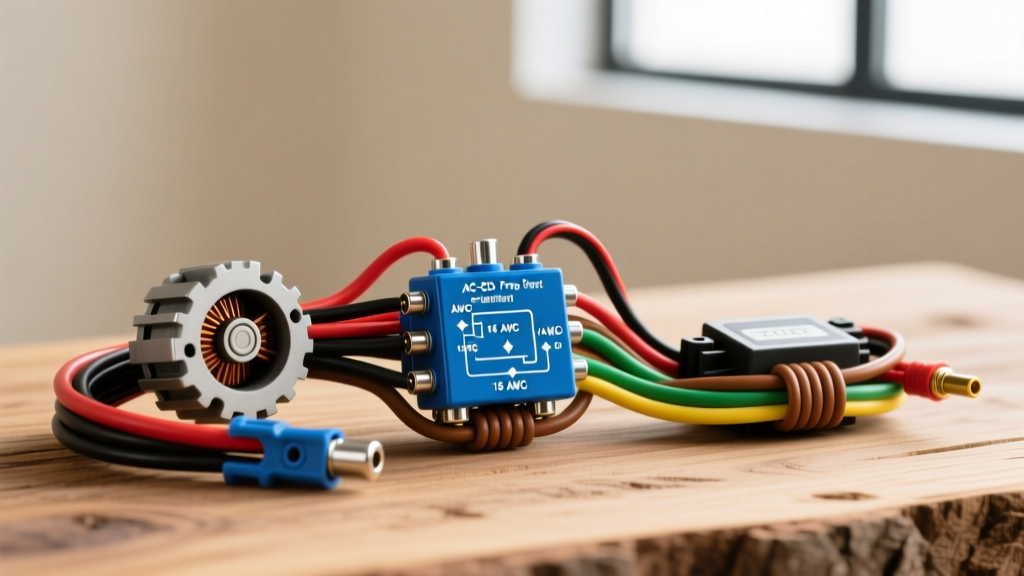
The Physics of Batteryless Ignition Systems
When searching for a without battery kick start simple motorcycle wiring diagram, most beginners get overwhelmed by complex factory harnesses designed to power headlights, horns, and electric starters. If you are building a vintage cafe racer, a minimoto, or a dedicated off-road machine, eliminating the heavy lead-acid battery saves weight and removes a primary point of failure. However, running a batteryless ignition requires a fundamental understanding of alternating current (AC) magneto systems.
Unlike modern fuel-injected motorcycles that rely on a 12V DC battery to power a DC-CDI or TCI (Transistor Controlled Ignition) module, a batteryless setup must use an AC-CDI unit or a traditional magneto. In this system, the kinetic energy of your kickstart turns the flywheel, which spins magnets past a stator source coil. This generates a high-voltage AC pulse (typically 100V to 400V AC) that is stored in the CDI’s internal capacitor and discharged into the ignition coil the exact millisecond the pickup coil signals it. According to Electrosport Technical Resources, understanding the separation between the ignition source coil and the lighting coil is the first step to a successful batteryless build.
Core Components for a Batteryless Setup
To execute this simple motorcycle wiring diagram, you must verify you have the correct hardware. A DC-CDI will not function without a 12V DC power source. You must source an AC-CDI. Here is the required component list:
- Stator with Ignition Source Coil: Must have a dedicated high-voltage AC winding (usually wrapped with thicker red/copper wire and insulated heavily) separate from the lighting coils.
- Pulse Pickup Coil (Trigger): A magnetic sensor mounted near the flywheel that reads the timing tab and tells the CDI when to fire.
- AC-CDI Module: A 5-pin or 6-pin shunt-type or capacitor discharge unit designed for AC input.
- Ignition Coil: A standard 12V motorcycle ignition coil (primary resistance 1.5 to 3.5 Ohms). Even though it is labeled "12V", it is triggered by the high-voltage CDI discharge, not a raw 12V battery.
- Resistor Spark Plug Cap: 5kΩ internal resistance to prevent electromagnetic interference (EMI) from scrambling the CDI’s internal thyristor.
Step-by-Step Wiring Execution
Follow this routing guide to create a clean, reliable harness. We recommend using SAE J1128 compliant primary wire for all connections to ensure the insulation can handle engine bay heat and vibration.
Step 1: Stator to CDI Routing
Run the stator wires through the engine case grommet. Use dielectric grease on the stator connector to prevent moisture ingress, which is a leading cause of weak spark on kickstart bikes. Connect the Black/Red (Source Coil) wire directly to the CDI’s Source pin. Connect the Blue/Yellow (Pickup Coil) wire to the CDI’s Trigger pin. The Green wire from the stator is your dedicated ignition ground; route this directly to the engine block, not the frame.
Step 2: CDI to Ignition Coil
The CDI outputs a massive voltage spike (up to 400V) to the primary side of the ignition coil. Connect the CDI’s Black/Yellow output wire to the positive terminal of the ignition coil. Connect the negative terminal of the ignition coil to a clean, bare-metal ground on the cylinder head.
Step 3: The Kill Switch Integration
This is where beginners make critical errors. On a DC system, a kill switch breaks the power circuit. On an AC-CDI system, the kill switch works by grounding the CDI’s kill circuit to stop the capacitor from discharging. Connect a momentary push-button switch between the CDI’s Black/White (Kill) wire and the chassis ground. When you press the button, the CDI shorts to ground, killing the spark.
Wire Gauge, Color Code, and Pinout Reference
Adhering to standard Japanese (Honda/Yamaha) color codes and proper AWG sizing prevents voltage drop and harness meltdowns. Reference the table below for your 5-pin AC-CDI harness.
| Function | Standard Wire Color | Recommended AWG | Connection Point |
|---|---|---|---|
| Source Coil (AC Input) | Black with Red Stripe | 16 AWG (High Voltage) | Stator Source to CDI Pin 1 |
| Pickup / Trigger Coil | Blue with Yellow Stripe | 18 AWG | Stator Pickup to CDI Pin 2 |
| Ignition Ground | Green | 14 AWG | Stator / CDI Pin 3 to Engine Block |
| Kill Switch Circuit | Black with White Stripe | 16 AWG | CDI Pin 4 to Ground (via Switch) |
| Coil Discharge Output | Black with Yellow Stripe | 14 AWG | CDI Pin 5 to Ignition Coil (+) |
Stator and Coil Resistance Diagnostics
Before wrapping your harness in split-loom or braided sleeving, you must verify the health of your magneto components. A kickstart system requires a healthy stator to generate enough initial voltage at low RPM. Use a digital multimeter (DMM) to test the following:
- Source Coil Resistance: Set DMM to 2kΩ. Measure between the Black/Red wire and the Green ground. Expect a reading between 320Ω and 380Ω (varies slightly by model, e.g., Honda CT90 vs. Yamaha DT125). If it reads OL (Open Loop), the internal winding is broken.
- Pickup Coil Resistance: Set DMM to 200Ω. Measure Blue/Yellow to Green. Expect 90Ω to 120Ω. A reading of near zero indicates a shorted coil.
- Ignition Coil Primary: Set DMM to 200Ω. Measure across the coil's two small spade terminals. Expect 1.5Ω to 3.0Ω.
- Ignition Coil Secondary: Set DMM to 20kΩ. Measure from the spark plug wire terminal to the coil mounting bracket. Expect 10,000Ω to 15,000Ω (10k - 15kΩ).
Troubleshooting Decision Tree: No Spark on Kickstart
If you have followed this without battery kick start simple motorcycle wiring diagram and still have no spark, use this expert diagnostic tree. Do not blindly replace the CDI; 90% of no-spark issues are grounding or flywheel related.
Symptom: Weak, intermittent orange spark
- Cause 1: Poor flywheel magnetism. If the bike sat for years, the flywheel magnets may have degraded. Fix: Test magnet strength with a steel screwdriver; replace flywheel if weak.
- Cause 2: High resistance in the ground path. Fix: Sand the ignition coil mounting bracket down to bare, shiny metal. Apply anti-oxidant paste, then torque to 8 Nm.
- Cause 3: Fouled spark plug cap. Fix: Unscrew the plug cap and measure resistance. Replace if it exceeds 7kΩ.
Symptom: Absolutely zero spark, even when kickstarting vigorously
- Cause 1: Kill switch is shorted to ground. Fix: Disconnect the Black/White wire from the CDI completely. If spark returns, your kill switch wiring is pinched or wired incorrectly.
- Cause 2: Sheared flywheel woodruff key. Fix: The flywheel has spun out of time, meaning the pickup coil is triggering at the wrong degree. Pull the flywheel and inspect the keyway.
- Cause 3: Failed Source Coil. Fix: Perform the resistance test outlined above. If the Black/Red wire has no continuity to ground, the stator must be replaced or rewound.
Symptom: Spark present, but engine backfires through carburetor on kick
- Cause 1: Incorrect pickup coil air gap. Fix: Use a brass feeler gauge to measure the gap between the pickup coil and the flywheel tab. Adjust to 0.012" - 0.016" (0.3mm - 0.4mm). Do not use steel feeler gauges, as they will stick to the magnet and give false readings.
- Cause 2: Swapped CDI pins. Fix: Verify the Source Coil and Pickup Coil are not reversed at the CDI connector. Reversing these will result in severe timing retardation and backfiring.
Final Assembly and Harness Protection
Once the engine fires and holds a steady idle via kickstart, secure your wiring. Because this simple motorcycle wiring diagram lacks a battery box, the CDI and harness are often exposed to the elements. Wrap the CDI connector in self-fusing silicone tape to create a waterproof seal. Route all ignition wires at least two inches away from the spark plug wire to prevent inductive crossfire, which can cause the engine to misfire at high RPMs. For more in-depth vintage harness restoration techniques, consult the 4into1 Honda CT90 Wiring Guide, which offers excellent visual references for magneto-based stator routing.