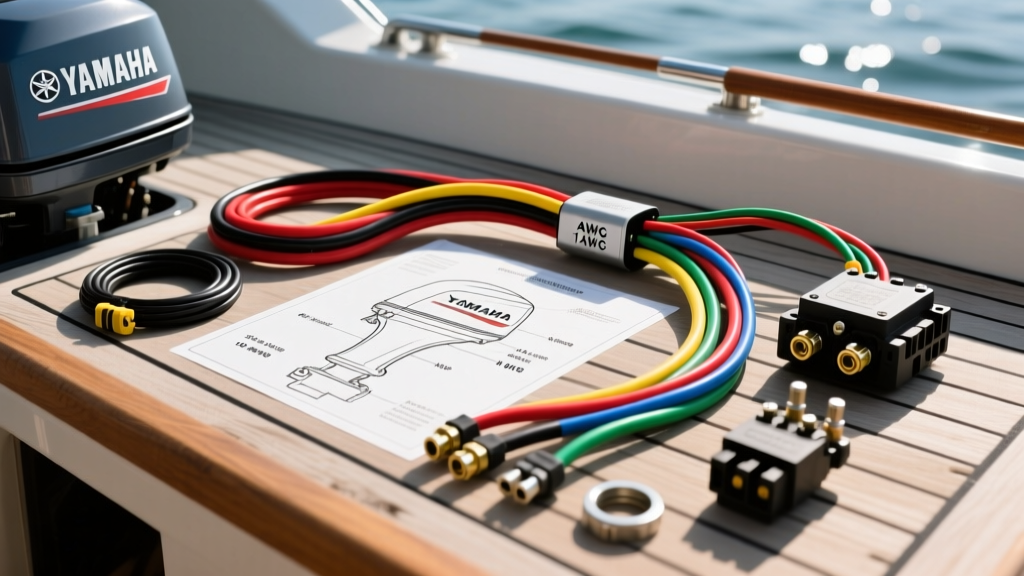
Introduction to Yamaha Marine Electrical Systems
When you first unroll a factory Yamaha outboard wiring diagram, the intricate web of lines, nodes, and alphanumeric codes can look like an alien language. Whether you are rigging a new center console, repowering a vintage aluminum hull, or simply troubleshooting a dead tilt/trim system, understanding these schematics is the bedrock of reliable marine electrical work. As a beginner, the most critical step is learning to translate Yamaha's proprietary symbols and color codes into actionable physical connections. This guide breaks down the fundamental architecture of Yamaha outboard harnesses, from the main battery cables to the delicate gauge cluster signals, ensuring your vessel remains safe and operational on the water.
Decoding Standard Yamaha Marine Wire Color Codes
Yamaha adheres to a relatively strict color-coding protocol across its 2-stroke and 4-stroke outboard families. While aftermarket harnesses might deviate, the OEM engine harness relies on these specific colors to route power, ground, and sensor data. Misinterpreting a green wire for a ground instead of a tachometer signal is a common beginner mistake that can instantly fry an expensive multifunction gauge. Always verify against the specific MarineEngine Outboard Schematics for your exact model year, but the following baseline colors apply to the vast majority of Yamaha outboards produced over the last three decades.
| Wire Color | Primary Function | Typical AWG Size |
|---|---|---|
| Red | Main Battery Positive (12V+ Unswitched) | 10 AWG to 4 AWG |
| Black | System Ground / Battery Negative | 10 AWG to 4 AWG |
| Yellow | Charge Output (Rectifier to Battery) | 10 AWG to 12 AWG |
| Green | Tachometer Signal (From CDI/Stator) | 16 AWG to 18 AWG |
| White | Speedometer Signal / Neutral Switch | 16 AWG to 18 AWG |
| Blue | Trim/Tilt Up Relay Trigger | 12 AWG to 14 AWG |
| Green/White | Trim/Tilt Down Relay Trigger | 12 AWG to 14 AWG |
| Brown | Accessory / Choke / Primer Solenoid | 14 AWG to 16 AWG |
The Helm Station: Ignition Switch Pinout and Harness Connections
The ignition switch is the central command hub for your boat's electrical system. Yamaha traditionally utilizes a standardized 6-pin or 7-pin round connector for the ignition harness. Understanding the terminal letters stamped on the back of the switch is crucial for troubleshooting a no-start condition or a parasitic battery draw. According to the BoatUS ABYC Wiring Guide, ensuring proper continuity through these terminals is the first step in diagnosing helm station failures.
Standard Yamaha 6-Pin Ignition Terminal Breakdown
| Terminal | Name | Function & Wiring Destination |
|---|---|---|
| B | Battery | Receives 12V+ from the main battery feed (Red wire). |
| I | Ignition | Sends 12V+ to the engine ECU/CDI and gauges when keyed ON. |
| C | Choke/Prime | Sends 12V+ to the primer solenoid or enriches the circuit for cold starts. |
| M | Magneto (Kill) | Grounds the ignition coil/CDI to kill the engine. Connects to Black/Yellow. |
| S | Start | Sends 12V+ to the starter solenoid trigger wire (Yellow/Red) when cranking. |
| A | Accessory | Powers auxiliary helm accessories (blower, stereo memory) independent of ignition. |
Troubleshooting Tip: If your Yamaha outboard cranks but will not fire, test the 'M' terminal. In the 'OFF' position, there should be continuity between 'B' and 'M' (grounding the ignition). In the 'ON' and 'START' positions, this continuity must break. If the 'M' circuit remains grounded while cranking, the engine is being intentionally killed by the switch or a faulty neutral safety switch.
Stator and Rectifier Diagnostics: The DVA Meter Requirement
One of the most expensive mistakes a beginner can make when reading a Yamaha outboard wiring diagram is attempting to test the stator and rectifier with a standard digital multimeter (DMM). Yamaha's charging and ignition systems rely on high-voltage, low-amperage AC pulses generated by the stator. A standard True-RMS multimeter will average these pulses, often displaying a reading of 12V to 20V AC, leading a DIYer to falsely conclude the stator is dead.
To accurately read a Yamaha wiring diagram's voltage specifications, you must use a DVA (Direct Voltage Adaptor) peak-reading meter. A DVA meter captures the peak voltage of the pulses. For example, a Yamaha lighting coil might specify 18V AC on a standard meter, but the CDI trigger coil might require a DVA reading of 150V to 400V. Always cross-reference the specific DVA voltage charts provided in the Yamaha factory service manual before ordering replacement charging components. For OEM replacement parts and specific model diagrams, Yamaha Outboard Parts remains the definitive resource for verifying part numbers and harness revisions.
Modern Networks: Yamaha Command Link Digital Wiring
If you are rigging a modern Yamaha 4-stroke (typically 2006 and newer), the traditional analog wire bundles are largely replaced by the Yamaha Command Link digital network. This multiplex system uses a CAN-bus style architecture to transmit engine data, fuel flow, and GPS speed over a single digital backbone.
- The Connectors: Command Link uses proprietary 3-pin square, waterproof connectors. Never attempt to splice or solder these digital cables; a broken shield wire will cause network-wide data dropouts.
- The Backbone: The network requires a main backbone cable with 120-ohm terminators at both physical ends of the line. Missing a terminator will result in erratic tachometer readings and ghost codes on your digital multifunction displays.
- Power T-Nodes: The network requires a dedicated 12V+ power insertion point (usually a red T-node connector) fused at 3 amps to power the digital gauges and engine ECU data bus.
Selecting Marine-Grade Wire and Connectors
When extending a Yamaha engine harness to the helm or battery bank, never use standard automotive copper wire. The marine environment demands tinned copper wire that meets UL 1426 and ABYC E-11 standards. The tin coating prevents the copper from oxidizing and turning black, which increases resistance and causes severe voltage drop over long cable runs typical in center console and offshore boats.
ABYC E-11 Compliance and Sizing
According to ABYC (American Boat and Yacht Council) standards, voltage drop on critical engine starting circuits should not exceed 3%, while non-critical accessory circuits can tolerate up to a 10% drop. Because outboard harnesses often run 15 to 25 feet from the transom to the helm and battery, you must upsize your wire. If a Yamaha diagram calls for 12 AWG for an accessory, but the run is 20 feet, step up to 10 AWG to compensate for the distance.
For all splices and harness extensions, abandon electrical tape and crimp caps. Use adhesive-lined, marine-grade heat shrink solder seals. The heat-activated adhesive creates a waterproof mechanical seal, while the solder ensures a permanent, low-resistance electrical bond that can withstand the constant vibration of an outboard motor mounted on the transom.