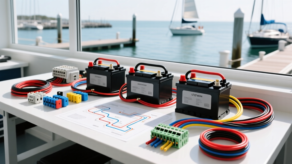
System Architecture: Twin-Engine + House Bank Topology
When marine technicians reference a 12 volt 3 battery boat wiring diagram, they are typically addressing a twin-engine cruiser, offshore center console, or heavy-displacement sailboat setup. This specific topology dedicates Battery 1 to the Port engine (cranking), Battery 2 to the Starboard engine (cranking), and Battery 3 to the House DC loads (deep cycle or lithium). Managing the charging logic and load isolation between three distinct 12V banks requires an Automatic Charging Relay (ACR) or a Voltage Sensitive Relay (VSR) wired to a centralized DC negative bus.
Failures in this system rarely stem from dead batteries; they are almost always traced to voltage drop, undersized ground conductors, or miswired ignition isolation circuits. According to the American Boat & Yacht Council (ABYC) E-11 standards, any misconfiguration in a multi-bank charging system can lead to alternator diode failure, parasitic drains, or catastrophic thermal events at high-current ring terminals.
Essential Diagnostic Tools & Safety Protocols
Before executing the troubleshooting flow, ensure you have the following equipment. Marine electrical systems operate in high-vibration, high-corrosion environments where standard automotive assumptions often fail.
- Digital Multimeter (DMM): Must be capable of measuring DC voltage to the hundredth decimal place (0.01V) for accurate voltage drop testing.
- DC Clamp Meter: Rated for at least 400A DC to measure cranking amps and alternator output without breaking the circuit.
- Carbon Pile Load Tester: To simulate heavy DC loads on the house bank and test ACR disconnect thresholds.
- Torque Wrench: 3/8-inch drive, capable of 5 to 15 ft-lbs for battery and ACR terminal hardware.
Safety Warning: Never disconnect a battery or ACR cable while the engine is running. Opening a live charging circuit can induce a voltage spike exceeding 50V, instantly destroying the alternator's rectifier diodes and sensitive engine control modules (ECMs).
Troubleshooting Decision Tree: Core Symptoms
Use the following step-by-step diagnostic flow to isolate faults in your 12 volt 3 battery boat wiring diagram. Identify your primary symptom and follow the conditional branches.
Symptom 1: House Bank (Battery 3) Not Charging Underway
Condition: Port and Starboard alternators are outputting 14.2V+ at their respective starting batteries, but the House bank remains at 12.6V or lower while underway.
- Step 1: Inspect ACR/VSR LED Status.
- Solid Green: Relay is combined. The fault is downstream (bad cable or corroded bus bar). Proceed to Step 3.
- Flashing Green / Off: Relay is not combining. The ACR does not see sufficient voltage to trigger the internal coil. Proceed to Step 2.
- Step 2: Verify ACR Ignition Isolation Wire.
Most premium ACRs (like the Blue Sea 7610) feature a blue 16 AWG ignition isolation wire. If this wire is improperly spliced into an 'always-hot' circuit instead of the ignition switch, the ACR may fail to combine correctly due to internal logic faults designed to protect alternators. Verify the blue wire reads 0V when the key is off, and 12V+ when the key is in the 'Run' position.
- Step 3: Perform Voltage Drop Test on the Positive Feed.
Set your DMM to DC Volts. Place the red probe on the alternator B+ post and the black probe on the ACR input post. With the engine at 1500 RPM, the reading must be less than 0.10V. If the drop is higher, the 1/0 AWG red marine cable is either undersized, internally corroded, or suffering from a loose crimp at the ring terminal.
Symptom 2: ACR/VSR Chattering or Clicking Rapidly
Condition: You hear a rapid mechanical clicking from the ACR relay while idling or at low RPMs, and the house bank voltage fluctuates wildly.
- Step 1: Analyze Alternator Voltage Regulator Logic.
Chattering occurs when the system voltage hovers exactly on the ACR's combine/disconnect threshold (typically 13.0V to combine, 12.75V to disconnect). When the ACR combines, the massive load of the depleted house bank pulls the system voltage down. If the alternator wire gauge is too small, the voltage at the ACR drops below 12.75V, causing the relay to open. The load disappears, voltage recovers to 13.0V, and the relay closes again.
- Step 2: Upgrade Alternator Output Wiring.
Check the wire gauge from the alternator to the starting battery. Many OEM marine builders use 4 AWG wire for 80A alternators. If you have upgraded to a 120A+ alternator, you must upgrade this wire to 2 AWG or 1/0 AWG to minimize voltage drop.
- Step 3: Install an External Sense Wire.
If upgrading the main cable does not stop the chattering, run a dedicated 10 AWG sense wire directly from the alternator's external sense terminal to the positive post of the starting battery. This forces the internal regulator to compensate for the voltage drop across the main cable, stabilizing the voltage fed to the ACR coil. For more on relay logic, refer to the Blue Sea Systems ACR Technical Reference.
Symptom 3: Port/Starboard Engine Cranks Slowly Despite Full Charge
Condition: Battery 1 and 2 test at 12.8V resting, but the starter motor engages sluggishly, and the DC voltage at the battery drops below 10.5V during cranking.
- Step 1: Isolate the Battery Switch.
Heavy-duty marine battery switches (e.g., Blue Sea 9001e) contain copper contactors that can carbonize over time. Place your DMM probes on the input and output posts of the battery switch. Have an assistant crank the engine. A voltage drop greater than 0.10V indicates internal switch failure or loose terminal nuts. Torque the 3/8-inch hardware to exactly 120 in-lbs (10 ft-lbs).
- Step 2: Inspect the DC Negative Return Path.
Marine technicians often focus entirely on the positive red cables. However, ABYC standards dictate that the negative return path must be equally robust. Check the 1/0 AWG yellow (or black) cable running from the engine block ground stud to the DC negative bus bar. Clean the mating surfaces with a wire brush and apply a dielectric grease (like Boeshield T-9 or No-Ox-Id) to prevent galvanic corrosion.
Reference Table: Marine Wire Gauge & Ampacity (ABYC E-11)
When repairing or modifying your 12 volt 3 battery boat wiring diagram, you must adhere to ABYC ampacity charts. Marine wire (UL 1426 / SAE J1128) features finer stranding and tinned copper to resist saltwater corrosion. Do not substitute automotive wire.
| AWG Size | Max Ampacity (105°C Insulation) | Typical Marine Application | Terminal Torque Spec (3/8 in.) |
|---|---|---|---|
| 4/0 AWG | 445A | Heavy Inverter/Charger to House Bank | 15 ft-lbs |
| 2/0 AWG | 384A | Main Battery Interconnects & Windlass | 12 ft-lbs |
| 1/0 AWG | 302A | ACR/VSR Feeds & Alternator B+ (High Output) | 10 ft-lbs |
| 2 AWG | 239A | Standard Alternator B+ & Battery Switch Feeds | 10 ft-lbs |
| 4 AWG | 183A | Panel Main Feeds & Bow Thruster Circuits | 8 ft-lbs |
| 10 AWG | 75A | ACR Ground Wire & Heavy Accessory Loads | 4 ft-lbs |
Advanced Diagnostics: Testing the Start Isolation (SI) Circuit
In a properly designed 3-battery diagram, cranking the Port engine should temporarily isolate the House bank to prevent voltage-sensitive marine electronics (chartplotters, VHF radios, sonar modules) from resetting due to the massive voltage sag of the starter motor. This is achieved via the Start Isolation (SI) terminal on the ACR.
The Diagnostic Test:
- Connect a 16 AWG green wire from the ACR SI terminal to the starter motor's 'S' (start) terminal.
- Turn the ignition key to 'Start' (cranking position).
- Measure the voltage at the ACR SI terminal. It should read 12V+.
- Simultaneously, monitor the ACR status. The relay should forcefully open, separating the House bank from the cranking battery, even if the starting battery voltage is above 13.0V.
- If the chartplotters still reboot during engine start, verify that the green SI wire is not mistakenly wired to an ignition 'Run' terminal, which would only provide 12V after the key is released from the 'Start' position.
Conclusion and Preventative Maintenance
A 12 volt 3 battery boat wiring diagram is only as reliable as its weakest crimp connection. Marine environments accelerate galvanic corrosion, particularly where dissimilar metals meet or where moisture wicks into unsealed ring terminals. Annually, remove all battery and ACR connections, clean them with a baking soda solution and a brass wire brush, and re-torque to the manufacturer's specifications. For comprehensive guidance on marine battery switch configurations and parallel bank management, review the BoatUS Marine Electrical Guide. By following this systematic troubleshooting flow, you can eliminate voltage drop, protect your alternators, and ensure your vessel's electrical system remains resilient on the water.