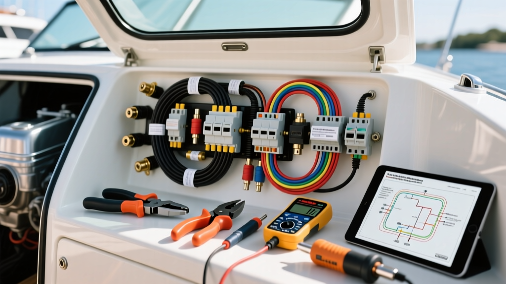
The Hidden Costs Behind Boat Wiring Diagrams
Reading boat wiring diagrams is only the first step in a marine electrical overhaul. While a schematic provides the logical roadmap for your vessel's DC and AC networks, translating those symbols into a physical, saltwater-resistant reality requires a significant investment in specialized tooling and marine-grade materials. Many DIY boaters underestimate the financial and technical gap between a standard automotive wiring harness and a marine electrical system built to ABYC (American Boat & Yacht Council) E-11 standards. This comprehensive cost and tool analysis breaks down exactly what it takes to execute custom boat wiring diagrams safely, reliably, and to professional marine surveyor standards.
Essential Tooling: Capital Requirements for Marine Termination
You cannot execute professional boat wiring diagrams using hardware store crimpers and electrical tape. The harsh marine environment demands adhesive-lined heat shrink terminations to prevent capillary action and galvanic corrosion. To achieve this, specific tooling is mandatory.
Precision Crimping & Stripping Equipment
- Ancor Marine Grade Heat Shrink Crimper (Model 120110): Retailing around $45, this ratcheting crimper features specific dies designed for the thicker walls of adhesive-lined marine terminals. The ratchet mechanism ensures a gas-tight crimp that meets UL 486A pull-out test requirements.
- Knipex ErgoStrip Universal Stripping Tool: At approximately $55, this tool prevents nicking the delicate tinned copper strands of Type 3 marine wire. Nicked strands reduce the cross-sectional area, increasing resistance and creating localized heat spots under high continuous loads.
- Thermaltronics or Milwaukee M18 Heat Gun: A precision heat gun with a concentrator nozzle ($120-$180) is required to evenly shrink the polyolefin tubing and activate the internal meltable adhesive sealant without scorching the wire insulation.
Testing & Diagnostics Instrumentation
Verifying the physical build against your boat wiring diagrams requires more than a simple test light. A Fluke 117 True RMS Multimeter ($200) is the industry standard for measuring voltage drop across long cable runs and verifying the integrity of high-resistance ground paths. Additionally, a Midtronics PBT300 Battery and Alternator Tester ($130) is crucial for validating the output of marine alternators and the health of house battery banks before integrating them into complex distribution diagrams.
Material Cost Breakdown: Tinned Copper and Circuit Protection
The most significant variable cost when executing boat wiring diagrams is the wire itself. Marine environments mandate UL 1426 / SAE J1128 compliant, tinned, Type 3 stranding copper wire. Standard automotive untinned wire will rapidly oxidize, turning black and increasing resistance, which leads to catastrophic voltage drop and potential fire hazards. According to Ancor Products, premium marine wire commands a premium price, but it is non-negotiable for ABYC compliance.
| AWG Size | Primary Use Case (per Diagrams) | Max Ampacity (ABYC) | Avg. Cost Per Foot | Standard Color Codes |
|---|---|---|---|---|
| 16 AWG | Navigation lights, instruments, VHF radios | 15A (Engine Space) | $0.45 | Red (Pos), Black (Neg) |
| 12 AWG | Bilge pumps, blowers, cabin lighting | 25A (Engine Space) | $0.85 | Yellow (12V DC), Black |
| 8 AWG | Windlasses, inverters, large thrusters | 55A (Engine Space) | $2.10 | Red, Black |
| 2/0 AWG | Battery bank interconnects, starter motors | 220A (Engine Space) | $6.50 | Red, Black |
Fusing and Distribution Hardware
Boat wiring diagrams utilize specific symbols for circuit protection. Translating these symbols requires purchasing high-quality, ignition-protected marine distribution blocks. A Blue Sea Systems ST Blade Fuse Block (12 circuits) costs approximately $55 and features independent negative buses for each circuit, eliminating the need to daisy-chain ground wires—a common violation of ABYC E-11. For primary battery protection, Marine Rated Battery Fuses (MRBF) and their accompanying terminal blocks ($45 per set) are required to protect against dead-short scenarios directly at the battery post.
Translating Diagram Symbols to Real-World Voltage Drop Calculations
A frequent mistake when following boat wiring diagrams is sizing wire solely based on the ampacity chart without factoring in voltage drop over the total round-trip circuit length. ABYC standards dictate a maximum 3% voltage drop for critical circuits (navigation lights, electronics, bilge pumps) and a 10% drop for non-critical circuits (cabin lights, bait pumps).
Consider a diagram showing a 15A radar unit located 20 feet from the distribution panel. The total round-trip wire length is 40 feet. If you use 12 AWG wire (rated for 15A), the resistance of 40 feet of 12 AWG copper is approximately 0.064 ohms. Using Ohm's Law (V = I x R), the voltage drop is 15A x 0.064 ohms = 0.96 Volts. On a 12.6V system, this represents a 7.6% drop. This fails the 3% critical circuit requirement. To execute the diagram correctly, you must step up to 8 AWG wire, dropping the resistance to 0.025 ohms, yielding a 0.37V drop (2.9%), which passes ABYC inspection. This technical reality drastically alters your material budget, as 8 AWG wire costs nearly 150% more than 12 AWG.
Common Failure Modes and the Cost of Rework
Cutting corners on materials or tools when executing boat wiring diagrams inevitably leads to expensive failure modes. Understanding these risks highlights the ROI of doing it right the first time.
Galvanic Corrosion and Capillary Action
Using non-adhesive vinyl terminals or failing to seal the wire entry point allows moisture to wick inside the insulation via capillary action. This causes the copper to oxidize and turn to green powder (copper chloride), effectively acting as a resistor. The cost to trace, diagnose, and replace a corroded run inside a concealed hull cavity often exceeds $500 in labor and materials, dwarfing the $15 savings of using cheap automotive terminals.
Thermal Runaway from Poor Crimps
A loose crimp created by a non-ratcheting tool increases contact resistance. When a high-amperage device like a windlass or electric head draws current, this resistance generates intense heat. This can melt the terminal housing, cause a short to the bilge water, or start an electrical fire. As noted by Blue Sea Systems circuit protection guidelines, proper termination is the first line of defense in marine electrical safety.
Labor vs. DIY: Project Budgeting for a 24-Foot Center Console
To provide a realistic budget for executing a comprehensive set of boat wiring diagrams, consider a complete rewiring of a 24-foot center console. This includes a dual-battery setup with an Automatic Charging Relay (ACR), VHF radio, LED navigation lights, dual bilge pumps, and a 12-circuit DC distribution panel.
| Category | Item Description | Estimated Cost (DIY) |
|---|---|---|
| Tooling (Amortized) | Crimpers, strippers, heat gun, multimeter | $350.00 |
| Wire & Cable | 250 ft mixed AWG tinned marine wire | $285.00 |
| Terminations | Adhesive heat shrink rings, butts, quick connects | $85.00 |
| Distribution & Protection | Blue Sea panels, ACR, MRBF fuses, busbars | $420.00 |
| Conduit & Loom | Split loom, cable ties, edge protection | $65.00 |
| Total DIY Material | Excluding source batteries and major electronics | $1,205.00 |
By comparison, a professional marine electrician charging $125 per hour will typically quote between $3,500 and $5,500 for the same scope of work, factoring in shop overhead, liability insurance, and the meticulous labor required to route, label, and secure wires every 18 inches per ABYC standards. For the technically inclined DIYer willing to invest in the proper tooling and study the boat wiring diagrams thoroughly, the financial savings are substantial, provided the execution meets marine-grade safety thresholds.
Final Verification and Sea Trial Testing
Once the physical installation matches the boat wiring diagrams, the final step is load testing. Do not rely on open-circuit voltage readings. Turn on all critical DC loads simultaneously—radar, VHF, nav lights, and bait pumps—and measure the voltage at the furthest device in the circuit. If the voltage remains above 12.2V at the equipment terminals under full load, your wire sizing and termination execution are successful. Properly executed marine wiring is an investment in the vessel's safety, longevity, and ultimate resale value, making the initial tool and material costs entirely justifiable.