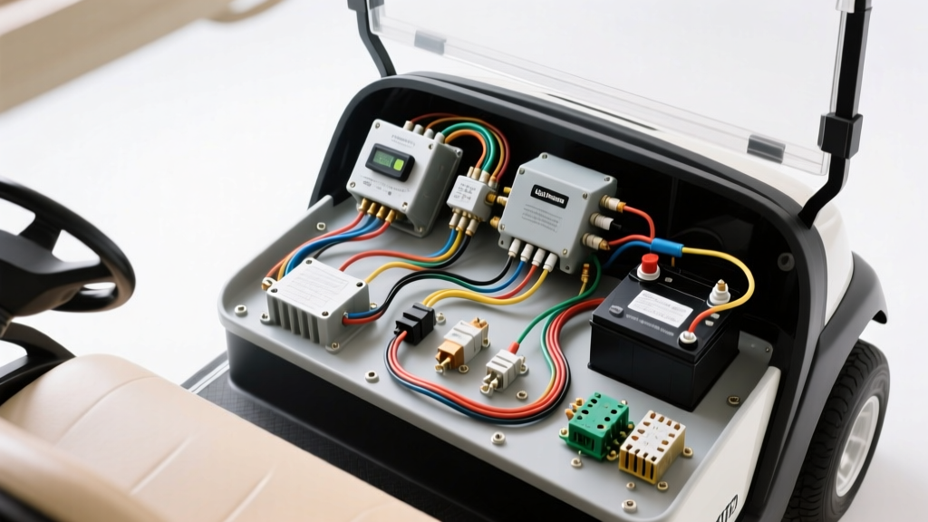
Mastering the Club Car Carryall Electric Wiring Diagram
The Club Car Carryall series (including the 100, 300, 500, and 700 electric models) represents the pinnacle of utility vehicle engineering in the light electric vehicle (LEV) space. Unlike standard passenger golf carts designed for flat fairways, the Carryall lineup requires high-torque motor configurations, heavy-duty solenoid switching, and robust controller logic to manage towing, off-road terrain, and heavy payload demands. Understanding the Club Car Carryall electric wiring diagram is essential for technicians and fleet managers looking to perform accurate diagnostics, execute controller upgrades, or troubleshoot high-current failures.
This comprehensive walkthrough dissects the 48-volt electrical architecture, focusing on the industry-standard Curtis 1268 motor speed controller, the Inductive Throttle System (ITS), and the Advanced DC (ADC) motor routing. We will cover exact wire color codes, AWG specifications, torque values, and real-world failure modes based on SAE J1128 low-tension cable standards and OEM service data.
Main Power Distribution and Battery Bank Configuration
The heart of the Carryall electric powertrain is the 48V nominal battery bank, typically configured using eight 6V deep-cycle flooded lead-acid batteries (e.g., Trojan T-105 or US Battery US2200) wired in series. Because utility vehicles experience severe current spikes during heavy towing or steep incline starts, the main power cabling must minimize voltage drop.
- Cable Specification: 2 AWG stranded copper welding cable is mandatory for all main series links and the primary feed to the solenoid. Using 4 AWG or smaller on the main bus will result in excessive heat generation and voltage sag under load.
- Terminal Preparation: All battery posts and cable lugs must be treated with a NO-OX-ID or equivalent anti-oxidant conductive paste to prevent sulfuric acid corrosion.
- Torque Specifications: Hardware on 5/16-inch battery terminal bolts must be torqued to exactly
110 in-lbs(9.1 ft-lbs). Under-torquing causes arcing and melted lead posts; over-torquing strips the soft lead threads.
The main positive feed (Red, 2 AWG) routes from the battery pack positive terminal to the input side of the main heavy-duty solenoid. The main negative (Black, 2 AWG) routes directly from the battery pack negative to the controller's B- busbar.
The Curtis 1268 Controller Pinout Walkthrough
Modern Club Car Carryall electric models rely heavily on the Curtis 1268 (or newer 1236) programmable motor speed controller. This unit manages pulse-width modulation (PWM) for speed control, regenerative braking logic, and thermal rollback protection. Below is the critical pinout and wiring reference for the high-current and logic connections.
| Controller Pin / Busbar | Function | Wire Color | AWG Size | Destination / Notes |
|---|---|---|---|---|
| B+ (Main Stud) | Battery Positive Input | Red | 2 | Output side of Main Solenoid |
| B- (Main Stud) | Battery Negative Return | Black | 2 | Battery Pack Main Negative |
| M- (Main Stud) | Motor Armature Negative | Blue | 2 | Motor Terminal A2 |
| A1 (Main Stud) | Motor Armature Positive | Yellow | 2 | F/R Switch Center Tap / Motor A1 |
| A2 (Main Stud) | Motor Field / Armature Return | Green | 2 | F/R Switch Center Tap / Motor S2 |
| Pin 8 (Logic) | Key Switch / Tow-Run Input | Red/White | 16 | Key Switch Output (48V Logic Feed) |
| Pin 12 (Logic) | Forward Microswitch Input | Blue/White | 18 | F/R Switch Forward Microswitch |
| Pin 13 (Logic) | Reverse Microswitch Input | Yellow/White | 18 | F/R Switch Reverse Microswitch |
For detailed programming parameters and thermal rollback thresholds, technicians should consult the Curtis Instruments technical datasheets and utilize the Curtis 1311 handheld programmer to read active fault codes (e.g., HPD - High Pedal Disable).
Solenoid, Precharge, and High-Current Switching
The main solenoid (typically an Albright SW80 or Trombetta 48V industrial contactor) acts as the primary high-current switch. When the key is turned and the throttle is pressed, the controller grounds the solenoid coil, pulling the contacts closed and delivering 48V to the controller's B+ stud.
The Precharge Circuit: To prevent the massive inrush current from welding the solenoid contacts or blowing the controller's internal capacitors, a precharge circuit is installed. This consists of a 470-ohm, 2-watt resistor (or a specialized precharge diode assembly on newer models) wired in parallel across the solenoid's large terminals. When the key switch is turned on, a small trickle current flows through the resistor, equalizing the voltage across the controller capacitors before the main solenoid clicks closed. If your solenoid clicks but the cart immediately throws a low-voltage controller fault, check the precharge resistor for an open circuit.
Inductive Throttle System (ITS) Calibration and Wiring
Club Car utilizes a non-contact Inductive Throttle System (ITS) rather than a traditional potentiometer. The ITS uses a Hall-effect sensor mounted in a plastic housing on the pedal box, reading the position of a rotating magnet attached to the accelerator pedal shaft.
- Black Wire (Ground): Provides the 0V reference from the controller's 15V regulator.
- Red Wire (Supply): Carries a precise
15.0V DCexcitation voltage from the controller. - White Wire (Signal): Returns the variable voltage signal to the controller's analog input pin.
Diagnostic Testing: With the key ON and the run/tow switch in RUN, backprobe the White signal wire. At rest (pedal released), the voltage should read between 0.7V and 0.9V. As the pedal is depressed to wide-open throttle (WOT), the voltage should smoothly sweep up to 3.1V - 3.4V. Any erratic jumps in voltage indicate a failing Hall sensor or a loose magnet on the pedal pivot.
Forward/Reverse Switch and ADC Motor Routing
The Carryall electric models utilize an Advanced DC (ADC) motor, which features separate armature and field windings to allow for regenerative braking and precise speed control. The Forward/Reverse (F/R) switch is a heavy-duty DPDT (Double Pole, Double Throw) rocker switch that physically reverses the current flow through the motor's stator field windings relative to the armature.
The Yellow (2 AWG) and Green (2 AWG) cables from the controller route to the outer terminals of the F/R switch. The center terminals route directly to the motor's S1 and S2 field posts. Microswitches mounted on the back of the F/R rocker assembly send 48V logic signals to Pins 12 and 13 on the Curtis controller, informing the brain of the selected direction before it enables the main MOSFET drive bridge.
Tow/Run Switch and Regenerative Braking Logic
Located under the seat near the controller, the Tow/Run switch is a critical safety and preservation device. When set to TOW, it physically interrupts the 48V logic feed to the controller and disables the regenerative braking circuit. This prevents the controller's internal voltage regulator from slowly draining the battery pack during long-term storage. More importantly, it prevents the motor from generating back-EMF (electromotive force) while the vehicle is being towed by a truck, which could otherwise fry the controller's power transistors.
Advanced Troubleshooting Decision Tree
When diagnosing a no-start or low-power condition on a Club Car Carryall electric, follow this structured diagnostic path:
- Symptom: Solenoid does not click.
Cause: Failed F/R microswitch, blown 15V controller fuse, or Tow/Run switch left in TOW.
Fix: Verify 48V at Pin 8. Check microswitch continuity. Ensure ITS magnet is within 2mm of the sensor. - Symptom: Solenoid clicks, but cart does not move (No fault codes).
Cause: Open circuit in the motor field windings or a disconnected A2 cable.
Fix: Perform a continuity test between Motor S1 and S2. Inspect the F/R switch heavy lugs for thermal melting. - Symptom: Cart moves but lacks torque and triggers thermal rollback.
Cause: High resistance on the B+ or B- main busbars, or severely sulfated battery interconnects.
Fix: Perform a loaded voltage drop test across all 2 AWG cables. A drop greater than0.2Vacross any single cable under load indicates a failed crimp or corroded terminal.
For comprehensive OEM schematics and fleet maintenance schedules, always refer to the official Club Car Support Documentation portal to ensure your wiring modifications align with factory safety standards.