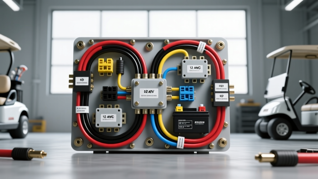
Critical Safety Warnings for the 48V AC RXV Platform
The E-Z-GO RXV (2008-present) revolutionized the golf cart industry by introducing a 48V AC drive system, regenerative braking, and an integrated DC-DC converter. However, the complexity of this platform means that misinterpreting the 48v ezgo rxv 48 volt wiring diagram can lead to catastrophic component failure, electrical fires, or severe arc flash injuries. Before touching a single terminal, you must understand the high-current dynamics of the RXV's Danaher or Curtis 1238AC controller.
Arc Flash and Capacitor Discharge Protocols
The main controller in an RXV contains massive electrolytic capacitors designed to handle high-frequency AC motor switching. When the main solenoid engages, these capacitors charge almost instantaneously. If you are troubleshooting or modifying the wiring, simply turning the key off is not enough. You must:
- Set the Tow/Run switch to 'Tow' to disable the controller's internal logic.
- Disconnect the main negative battery cable first.
- Wait a minimum of 5 minutes for the controller capacitors to bleed down through the internal discharge resistors.
- Verify zero voltage across the controller's B+ and B- terminals using a CAT III rated multimeter before touching any high-current lugs.
Top 5 Wiring Mistakes on the RXV 48V Diagram
Even seasoned technicians make critical errors when rushing through an RXV controller swap or battery pack rebuild. Here are the most common and destructive mistakes found in the field.
Mistake 1: Bypassing the Pre-Charge Circuit
The most frequent error when following a generic 48v ezgo rxv 48 volt wiring diagram is omitting the pre-charge resistor. The RXV uses an Albright SW200 or White-Rodgers 586 main solenoid. When the solenoid closes, the inrush current required to charge the controller's dead capacitors can exceed 400 amps for a fraction of a second. Without a 47-Ohm, 50-Watt wirewound pre-charge resistor wired in parallel across the solenoid's main high-current terminals, this massive spark will pit, melt, and eventually weld the solenoid contacts shut. A welded solenoid means the cart will remain powered on even with the key removed, leading to runaway scenarios or total controller destruction.
Mistake 2: Incorrect Solenoid Coil Diode Orientation
The solenoid coil is a massive inductor. When the controller cuts power to the small activation terminals (usually 36V or 48V depending on the exact coil spec), the collapsing magnetic field generates a high-voltage inductive kickback. A 1N4004 or 1N5408 flyback diode must be installed across the small coil terminals to absorb this spike. If the diode is installed backward (cathode band facing the negative/ground terminal), it will create a dead short across the coil driver the moment the solenoid engages, instantly frying the internal MOSFETs on the controller's logic board. Always ensure the diode's cathode band points toward the positive activation terminal.
Mistake 3: Undersizing Main Battery Cables (AWG Errors)
Many DIYers attempt to reuse old 6 AWG cables from a 36V TXT cart when upgrading or rewiring an RXV. According to the SAE J1128 Standard for low-tension primary cable, 6 AWG wire is entirely insufficient for the 300+ amp peak draw of an RXV AC motor under heavy load or hill climbs. Using undersized cables causes severe voltage drop. When the voltage at the controller's B+ terminal drops below the low-voltage cutoff (typically around 42V for a 48V pack), the controller will throw an HPD (High Pedal Disable) or Under-Voltage fault, leaving you stranded. You must use a minimum of 2 AWG stranded copper for the main battery loop, and 1/0 AWG is highly recommended for performance builds or lifted carts with larger tires.
Mistake 4: The 16V Accessory Tap Fallacy
The RXV battery pack typically consists of six 8V deep-cycle batteries wired in series (or four 12V batteries). A dangerous and all-too-common mistake is tapping into two 8V batteries in series to create a 16V power source for lights, radios, or lift kits. This unbalanced discharge will cause those specific batteries to sulfate and fail prematurely, ruining the entire $1,500+ battery pack. The 48v ezgo rxv 48 volt wiring diagram strictly dictates the use of a 48V to 12V DC-DC Converter (rated for at least 16A to 30A) wired directly to the main B+ and B- bus bars to ensure the entire pack is drawn from evenly.
Mistake 5: Miswiring the AC Motor Phase Sequence
Unlike older DC series motors where swapping two brushes changed the direction, the RXV's AC induction or permanent magnet AC motor relies on the controller to dictate phase sequencing (U, V, W). If you are replacing the motor or controller and accidentally swap the U and V phase cables, the motor will spin in reverse when the F/R switch is in the Forward position. More critically, if the 10k NTC motor temperature thermistor wires are pinched or misconnected to a high-current terminal, the Curtis AC Controller will read an open circuit, assume the motor is overheating, and immediately derate the cart's speed to 2 MPH to protect the windings.
RXV 48V High-Current Cable & Termination Specification Chart
Proper termination is just as critical as wire sizing. A loose lug creates resistance, which generates heat and melts the insulation. Always use a hydraulic or heavy ratcheting crimper for 2 AWG and larger cables, and finish with adhesive-lined heat shrink to prevent moisture intrusion and corrosion.
| Cable Route | Minimum AWG Size | Lug Type & Stud Size | Torque Specification |
|---|---|---|---|
| Battery Series Links | 2 AWG (or OEM Bridge) | 5/16' Ring Terminal | 75 in-lbs (8.5 Nm) |
| Main Pack (+) to Solenoid | 2 AWG (1/0 Preferred) | 3/8' Heavy Duty Ring | 90 in-lbs (10.2 Nm) |
| Solenoid to Controller B+ | 2 AWG (1/0 Preferred) | 3/8' Heavy Duty Ring | 120 in-lbs (13.5 Nm) |
| Controller B- to Main Pack (-) | 2 AWG (1/0 Preferred) | 3/8' Heavy Duty Ring | 120 in-lbs (13.5 Nm) |
| Controller U/V/W to Motor | 4 AWG Flex Silicone | 5/16' Ring or Stud | 75 in-lbs (8.5 Nm) |
| DC-DC Converter Input | 8 AWG | 1/4' Ring Terminal | 45 in-lbs (5.1 Nm) |
F/R Switch and Throttle Sensor (ITS) Calibration
The RXV utilizes an Inductive Throttle Sensor (ITS) rather than a traditional potentiometer found on older EZGO models. The ITS operates on a varying frequency signal rather than a 0-5V analog voltage drop. When rewiring the ITS connector, ensure the 3-pin harness (5V supply, Ground, Signal) is completely sealed. A common mistake is using standard butt-splices instead of OEM Deutsch or Molex connectors for the throttle harness. Moisture ingress into a poor splice will alter the frequency signal, causing the cart to surge or throw an ITS out-of-range fault code (often indicated by a specific sequence of flashes on the controller LED or tow/run switch).
Similarly, the Forward/Reverse switch on the RXV is a multi-pole directional switch that sends specific logic signals to the controller. If the microswitches inside the F/R housing are misaligned or wired to the wrong controller pins, the regenerative braking profile will be disabled, causing the cart to freewheel dangerously when going downhill in reverse.
Final Verification Steps
Before applying power after executing any repair based on the 48v ezgo rxv 48 volt wiring diagram, perform a continuity check. Use a multimeter to verify there is no dead short between the main B+ cable and the chassis ground. Once verified, reconnect the main negative battery, flip the Tow/Run switch to 'Run', and listen for the distinct, solid 'clack' of the main solenoid engaging when the key is turned and the pedal is pressed. For further reference on high-current contactor ratings, consult the Albright SW200 Contactor Specifications to ensure your replacement solenoid matches the continuous and intermittent amp draw requirements of your specific RXV motor configuration.