Upgrading Polaris Cars Electric Systems and UTV Platforms
When enthusiasts and fleet managers look into Polaris cars electric platforms, they are typically referring to the Polaris GEM (Global Electric Motorcars) series, the Polaris Ranger EV, or the electric-assist systems found in modern off-road utility vehicles. Unlike traditional internal combustion engine (ICE) side-by-sides that rely on a single 12V lead-acid battery and a stator-driven alternator, electric Polaris vehicles operate on high-voltage battery banks (typically 48V or 72V) paired with a DC-DC step-down converter to run 12V accessories. Upgrading these systems for heavy-duty accessories—such as high-lumen light bars, electric winches, or cab heaters—requires a fundamental understanding of high-amperage DC distribution, voltage drop mitigation, and battery pack balancing.
The Golden Rule: Never Tap a Single Battery in a Series Pack
The most catastrophic mistake made by amateur mechanics working on Polaris GEM e2, e4, e6, or Ranger EV models is tapping into a single 12V battery within the main series-wired battery bank to power a 12V accessory. In a 72V GEM system, six 12V batteries are wired in series. If you draw 10 amps from the first battery to run a stereo or lighting kit, that specific battery will discharge faster than the other five. When the onboard charger initiates a cycle, it pushes voltage through the entire series string. The five full batteries will overcharge, boil their electrolyte, and suffer sulfation, while the tapped battery remains chronically undercharged. This destroys a $2,000+ battery bank in a matter of weeks.
The Solution: You must always use a high-quality, isolated DC-DC voltage reducer (step-down converter) connected across the entire main battery pack (e.g., across the main positive and main negative terminals of the 48V or 72V bank). This ensures the load is drawn equally from all cells, maintaining pack equilibrium and adhering to the engineering standards outlined in the Polaris Official Service Manuals.
Sizing and Installing the DC-DC Step-Down Converter
Factory DC-DC converters in older Polaris EVs are often rated for only 10 to 15 amps, which is barely enough for the headlights, horn, and controller logic. When planning an upgrade project, install an aftermarket 30A or 50A continuous-duty DC-DC converter.
Input and Output Wiring Specifications
- Input Side (High Voltage): Use 8 AWG or 6 AWG stranded copper wire (compliant with SAE J1128 Low Tension Primary Cable standards) to connect the converter to the main battery pack. High-voltage DC requires robust insulation and minimal resistance to prevent voltage drop before the conversion stage.
- Output Side (12V Accessory): Use 10 AWG wire for the main 12V feed to your distribution bus bar.
- Fusing: Install a Class T or ANL fuse on the high-voltage input side (rated 25% higher than the max continuous draw) within 18 inches of the main battery positive terminal. On the 12V output side, use a maxi-fuse or mega-fuse block.
High-Current Bus Bar & Accessory Distribution
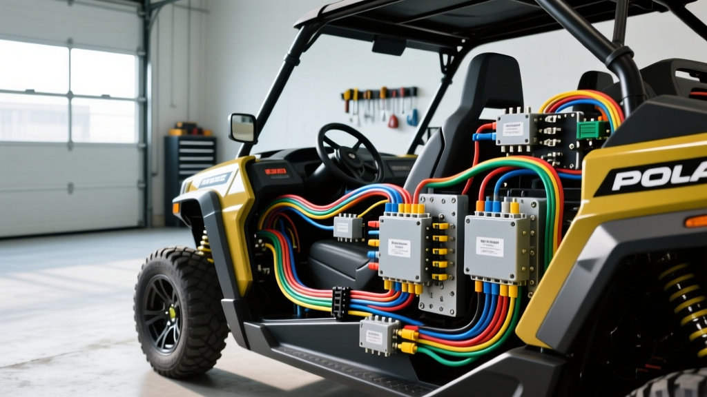
Running individual wires from the DC-DC converter to every accessory creates a rat's nest of connections and increases the risk of voltage drop. For Polaris cars electric modifications, the industry best practice is to install a marine-grade, tinned-copper bus bar system in a dry, ventilated area of the chassis (such as under the front hood or inside a sealed center console enclosure).
According to ABYC E-11 DC Electrical Standards (widely adopted for harsh-environment EV and off-road builds), bus bars must be mounted on non-conductive surfaces with adequate clearance. Use 3/8-inch stainless steel studs with marine-grade heat-shrink ring terminals. Torque the 5/16-inch or 3/8-inch ring terminal nuts to exactly 120 in-lbs (10 ft-lbs) to ensure a gas-tight connection without crushing the copper strands. Apply a dielectric grease or NO-OX-ID A-Special to the studs to prevent galvanic corrosion, especially on UTVs exposed to mud and water.
AWG Sizing and Voltage Drop Specification Chart
Because 12V systems are highly susceptible to voltage drop, wire gauge must be selected based on the total one-way wire length (from the bus bar to the accessory and back to ground) and the amperage draw. Use the following reference chart for your Polaris EV accessory builds:
| Max Amperage | 0 - 10 Feet | 10 - 20 Feet | 20 - 30 Feet | Recommended Fuse |
|---|---|---|---|---|
| 10A (LED Pods) | 16 AWG | 14 AWG | 12 AWG | 15A ATC |
| 20A (Light Bars) | 14 AWG | 12 AWG | 10 AWG | 25A ATC |
| 30A (Cab Heater) | 10 AWG | 8 AWG | 6 AWG | 40A Maxi |
| 50A (Winch Motor) | 4 AWG | 2 AWG | 1/0 AWG | 150A ANL |
Advanced Contactor Wiring with Pre-Charge Circuits
When wiring high-draw inductive or capacitive loads—such as a 4500-lb winch motor or a heavy-duty air compressor—to a Polaris EV, you cannot simply use a standard 12V automotive relay. The inrush current when the motor starts or the capacitors charge can exceed 200 amps for a fraction of a second, which will instantly weld the contacts of a standard 40A relay shut, creating a severe fire hazard.
Instead, use a heavy-duty continuous-duty solenoid (contactor) rated for at least 200A. However, to protect the contactor from arcing and pitting, you should wire a pre-charge circuit.
- Step 1: Wire a 50-ohm, 50-watt power resistor in parallel with the main contactor contacts.
- Step 2: When the driver flips the dashboard switch, a smaller 30A relay first engages the pre-charge resistor, allowing a small trickle of current to charge the accessory's capacitors and equalize the voltage across the main contactor.
- Step 3: A fraction of a second later, a time-delay relay (set to 0.5 seconds) triggers the main high-amperage contactor. Because the voltage is already equalized, the main contactor closes with zero arcing, vastly extending its lifespan.
Connector Selection: Anderson vs. Deutsch
For modular accessories on Polaris electric platforms, standard butt connectors and electrical tape are unacceptable. Use the following connector ecosystems:
- Anderson Powerpole SB50: Use these for high-current connections (up to 50A) such as winch quick-disconnects, trailer plugs, and removable battery packs. The red housing is standard for 12V, while gray or blue housings should be used for 48V/72V lines to prevent catastrophic cross-voltage plugging.
- Deutsch DT Series: Use these for all low-amperage sensor and lighting connections. The DT series is sealed to IP68 and handles up to 13A per pin. Pin 1 should always be designated for +12V switched power, and Pin 2 for ground, maintaining consistency across your custom wiring harness.
Troubleshooting EV Electrical Gremlins
Even with a flawless upgrade, Polaris EVs can present unique electrical symptoms. Use this diagnostic tree to resolve common issues:
- Symptom: DC-DC converter shuts off after 10 minutes of running LED lights.
Cause: Thermal overload. The converter is mounted in an area with zero airflow, or the ambient temperature inside the engine bay/hood exceeds 140°F (60°C).
Fix: Relocate the converter to the front grill area for ram-air cooling, or install a dedicated 12V cooling fan tied to the converter's output. - Symptom: Vehicle controller throws a low-voltage error code, but main battery pack reads 72V.
Cause: Voltage drop across the main battery interconnect cables due to corrosion on the series links.
Fix: Disconnect the pack, wire-brush all lead posts, apply anti-oxidant paste, and retorque the interconnect bolts to 120 in-lbs. Verify voltage drop across each individual cable under load; it should not exceed 0.05V. - Symptom: 12V accessories flicker when the drive motor accelerates.
Cause: The DC-DC converter is undersized and cannot maintain 13.8V output when the main pack voltage sags under heavy acceleration load.
Fix: Upgrade to a wider input-voltage DC-DC converter (e.g., 36V-96V input) that features active output regulation, ensuring a steady 14.1V output regardless of main pack voltage sag.
By treating your Polaris electric vehicle not just as a UTV, but as a high-voltage mobile power station, you ensure that your lighting, winching, and comfort accessories operate reliably for years to come without compromising the integrity of the main traction battery pack.