Demystifying the Polaris 'Pulse Bar' and Accessory Bus
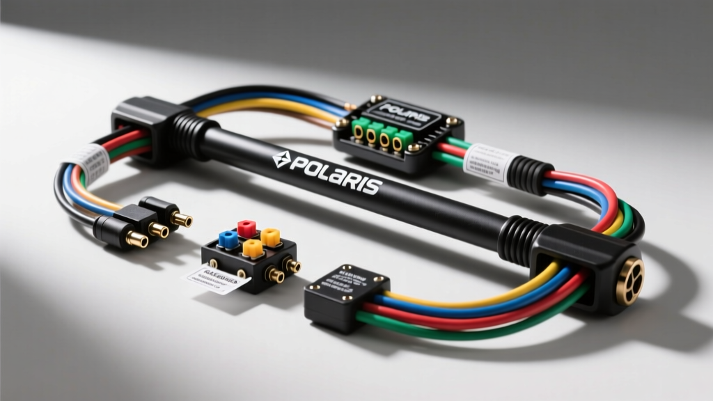
When beginners first dive into off-road electrical modifications, searching for a polaris pulse bar wiring diagram often leads to confusion. This is because 'pulse bar' is a colloquial misnomer that blends two distinct Polaris electrical systems: the factory Accessory Bus Bar (Terminal Block) and the Pulse Width Modulation (PWM) lighting circuits found on modern RZR, Ranger, and Sportsman models. Understanding how these two systems interact is the foundational first step to safely wiring light bars, rock lights, and low-draw accessories without melting your factory harness or draining your battery.
The factory accessory bus bar is a centralized terminal block designed to provide clean, switched, and constant 12V power sources. However, because Polaris utilizes PWM signals for dashboard dimming and certain OEM LED lighting circuits, connecting standard aftermarket LED drivers directly to a 'pulsed' circuit will result in severe flickering or premature driver failure. This guide will break down the exact pinouts, wire colors, and relay bypass strategies required to master your Polaris electrical system.
Factory Bus Bar Pinout and Wire Color Codes
Located under the hood near the battery or behind the center dash panel (depending on your specific Ranger or RZR model year), the accessory bus bar features several M6 threaded studs. Below is the standard Polaris terminal configuration. Always verify with a multimeter before connecting, as OEM harness revisions can occasionally swap secondary switched circuits.
| Terminal Type | Wire Color | Function | Max Amperage |
|---|---|---|---|
| Constant 12V (+) | Red | Direct battery power. Hot at all times. Used for memory circuits or direct relay feeds. | 30A (Fused) |
| Switched 12V (+) | Red/Yellow or Orange | Keyed power. Active only when the ignition is in the 'ON' or 'ACCESSORY' position. | 10A - 15A |
| PWM / Pulse Signal | Yellow or White | Pulse Width Modulated signal for OEM LED dimming. Do NOT use for standard relays. | 5A |
| Ground (-) | Black | Chassis ground return path. | 30A |
The PWM 'Pulse' Problem: Why Your LED Lights Flicker
Modern Polaris UTVs use Pulse Width Modulation (PWM) to control the brightness of OEM LED light bars and dash illumination. Instead of lowering the voltage, the ECU rapidly cycles the 12V signal on and off (typically at 200-400 Hz). While incandescent bulbs smooth this out via thermal inertia, aftermarket LED drivers interpret this rapid pulsing as a faulty power supply, resulting in a strobe-like flicker.
The Solution: The ISO Relay Bypass. To use the factory switched circuit without inheriting the PWM pulse, you must use a standard 4-pin Mini ISO relay. The relay's internal electromagnet requires a steady current to pull the contact closed. By wiring the relay coil to the bus bar, you isolate the high-draw LED driver from the sensitive PWM circuitry. For a deeper understanding of automotive relay standards, refer to the Littelfuse Mini ISO Relay Datasheet.
Step-by-Step: Wiring an Accessory via the Bus Bar
Follow this beginner-friendly sequence to wire a standard LED light bar (drawing under 15 amps) using the factory bus bar as your trigger and power distribution point.
- Disconnect the Battery: Use a 10mm wrench to remove the negative (-) battery terminal. This prevents accidental shorting against the chassis while working near the bus bar.
- Prepare the Relay Harness: Obtain a weatherproof 4-pin relay socket with pre-crimped pigtails.
- Pin 86 (Coil +): Connect to the Switched 12V (Red/Yellow) bus bar terminal.
- Pin 85 (Coil -): Connect to the Ground (Black) bus bar terminal.
- Pin 30 (Common): Connect to the Constant 12V (Red) bus bar terminal.
- Pin 87 (Normally Open): Run this to the positive lead of your LED light bar.
- Terminate the Connections: Slide adhesive-lined heat shrink over your wire ends before crimping the M6 ring terminals. According to SAE J1128 standards, adhesive heat shrink provides the necessary moisture barrier to prevent galvanic corrosion in off-road environments.
- Torque the Hardware: Place the ring terminals onto the bus bar studs. Secure them with the factory M6 flange nuts. Torque to 5-7 Nm (44-62 in-lbs). Overtightening will strip the brass studs; undertightening will cause arcing and voltage drop.
- Weatherproof: Apply a liberal coating of dielectric grease over the exposed terminals and nuts to seal out moisture and prevent white oxide buildup.
Wire Gauge (AWG) and Hardware Specifications
Selecting the correct wire gauge is critical. Using wire that is too thin causes voltage drop, resulting in dim lights and melted insulation. Always use stranded, copper primary wire (never solid core household wire, which will snap under UTV vibration).
| AWG Size | Max Amperage (Chassis Wiring) | Recommended Use Case |
|---|---|---|
| 14 AWG | 15 Amps | Relay trigger wires, rock lights, dash switches. |
| 12 AWG | 20 Amps | Standard 30-inch LED light bars, small fuel pumps. |
| 10 AWG | 30 Amps | Large 50-inch LED bars, heated grips, 12V accessory sockets. |
| 6 AWG | 60+ Amps | Winch solenoid feeds, high-output stator upgrades. |
Critical Warning: Winches and the Accessory Bus Bar
A common and catastrophic beginner mistake is attempting to wire a 4500lb UTV winch directly through the accessory bus bar. A winch under load can pull 150 to 300 amps. The bus bar and its associated 12 AWG factory harness wires will instantly melt, potentially causing an electrical fire. The bus bar should ONLY be used to provide the low-amperage (under 5A) switched trigger signal to the winch's heavy-duty solenoid/contactor. The winch motor's main power cables (typically 6 AWG or 4 AWG) must be routed directly to the battery terminals or a dedicated high-amperage solenoid block. For official accessory routing guidelines, consult the Polaris Owner's Manuals and Service Documentation.
Troubleshooting Common Bus Bar Failures
If your newly installed accessories are malfunctioning, use this decision tree to diagnose the issue without resorting to cutting factory wires.
| Symptom | Probable Cause | Expert Fix |
|---|---|---|
| LED lights flicker rapidly or strobe. | Wired directly to a PWM / Pulse circuit instead of a standard switched 12V source. | Move the trigger wire to the Red/Yellow switched terminal and use an ISO relay. |
| Accessory stays on after key is removed. | Trigger wire connected to the Constant 12V (Red) terminal instead of Switched. | Relocate the relay coil trigger to the Switched (Red/Yellow) terminal. |
| Lights are dim; relay gets hot to the touch. | Voltage drop due to loose M6 bus bar nuts or undersized wire gauge. | Clean terminals with contact cleaner, re-crimp if necessary, and torque nuts to 5-7 Nm. |
| Factory dash lights dim when light bar turns on. | Overloaded the switched circuit; drawing more than 15A through the factory ECU driver. | Ensure you are using a relay. The bus bar should only carry the 0.5A relay coil load. |
Final Expert Tips for Long-Term Reliability
Off-road environments subject electrical connections to extreme G-forces, mud, and water submersion. Never rely on electrical tape to seal a connection; the adhesive will melt in the summer heat and unravel. Always use marine-grade adhesive heat shrink and high-quality ratcheting crimpers. By treating the Polaris accessory bus bar as a low-current trigger distribution hub rather than a high-current power source, you will build an electrical system that is both beginner-friendly and expedition-ready.