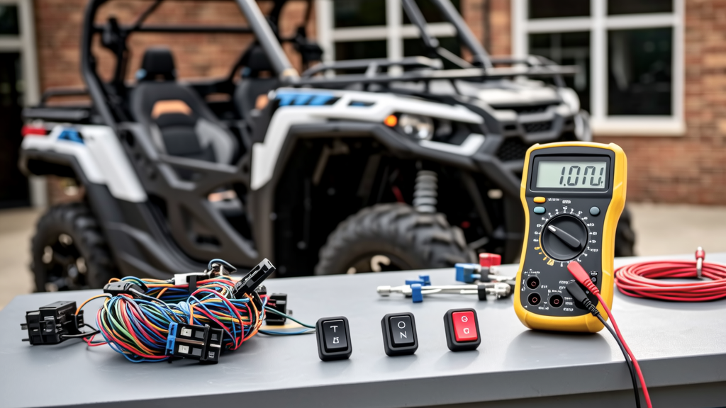
Summary: Matching a Cart With a Switch
Matching a cart to a switch is not a simple color or shape problem. It is an electrical compatibility task. A golf cart, UTV, or utility cart must be paired with a switch whose voltage rating, continuous current rating, interrupting capacity, connector type, mounting size, and environmental sealing fit the load and the operator. For 36V and 48V EZGO, Club Car, Yamaha, and ICON carts, use DC-rated switches with generous amp derating. For 12V Polaris, Can-Am, Segway, and Honda UTV systems, ignition and accessory switches need automotive-grade contacts. The safest method starts with the cart data plate, battery voltage, controller limits, and the function of the switch. Measure, record, and match before wiring.
Why Matching a Cart to a Switch Is an Electrical Decision
A switch is a control point, but it is also a contact surface that must make and break current repeatedly. When a cart has a 48V battery pack, a solenoid, a controller, lights, a charger, or a hydraulic lift, the switch sees more than a simple on or off. It sees inrush current, arc energy, vibration, heat, and moisture. A 12V automotive switch that works perfectly in a Polaris RZR may chatter or pit contacts in a Club Car DS 48V circuit. A light-duty toggle may feel fine in the hand while the copper inside overheats.
The failure pattern is usually slow and expensive. A switch that is under-rated may first cause dimming, a warm connector, a melted insulation sleeve, or a blown Littelfuse blade fuse. Then the contact resistance rises, the voltage drop increases, and a controller or solenoid starts behaving oddly. In golf carts, the controller is often the most expensive component. In UTVs, the ignition switch may be tied to the ECU, starter relay, and accessory circuit. Matching the switch to the cart protects both the control device and the operator.
The right match starts with the load. A 12V DC LED light bar drawing 18A is not the same as a 12V DC starter relay coil drawing 30A for two seconds. A 48V DC charger interlock that only switches a small signal current is not the same as a main battery disconnect rated for 300A. The same physical switch can be correct for one circuit and unsafe for another. Always read the cart wiring diagram and the switch datasheet, not just the label.
Start With the Cart: Voltage, Power, and Duty Cycle
Before selecting a switch, survey the cart as a system. Identify the nominal voltage, maximum available current, controller or solenoid ratings, wire gauge, fuse size, and how long the circuit is energized. A data plate may show 36V, 48V, or 60V for electric carts. A UTV may show 12V, but the alternator output and accessory fuse box can still supply high momentary current. Record all of it in a simple worksheet.
36V and 48V Golf Cart Systems
Most electric golf carts use 36V or 48V DC battery packs. An EZGO TXT can be configured with six 8V batteries for 48V, while many Club Car DS models also use 48V packs built from eight 6V Trojan T-105 batteries rated 225 Ah. Yamaha Drive and Drive AC carts commonly use 48V systems, and ICON i40L carts also operate at 48V DC, sometimes with LiFePO4 packs, with controller output that can exceed 300A during acceleration. If the switch controls the main power path, the rating must account for that surge.
For accessory circuits, a 48V golf cart may still use a 12V DC light bar or radio through a DC-DC converter, such as a 48V to 12V converter rated 10A. In that case, the switch can be 12V DC if it is downstream of the converter and protected by a 10A or 15A fuse. If the switch is directly across a 48V load, use a switch with a DC voltage rating of at least 48V and a current rating that leaves at least 30 percent margin for continuous duty.
12V UTV and ATV Systems
UTVs and ATVs usually run 12V DC systems. A Polaris RZR 1000, Can-Am Maverick X3, Segway Villain, or Honda Pioneer may use 12V key switches, 12V rocker switches, 12V toggle switches, and 12V accessory circuits. The alternator may supply 50A, and accessories can draw 500W to 850W or more depending on model and load. For ignition switches, the contact set that feeds the ECU, starter relay, and fuel pump can see repeated cycles and inductive spikes.
Do not assume a 12V rating is enough if the switch controls a motor, solenoid, hydraulic valve, winch, or high-output LED light. A winch solenoid on a Can-Am can draw tens of amps for seconds. A starter relay coil may be modest, but the starter itself can draw 200A to 400A. If the switch is only controlling the coil, it must still be rated for inductive loads. If the switch is directly controlling the motor, use a contactor or relay and let the switch only command the relay coil.
Match the Switch Function to the Load
Cart switches are not interchangeable just because they fit the dash. A key switch is not always a main disconnect, and a rocker switch is not always an ignition switch. A utility cart or shopping-style cart may need a simple momentary switch, while a UTV may need a detented rocker with a separate accessory position. The function determines the contact arrangement, actuator style, and safety expectations.
Ignition and Accessory Switches
Ignition switches usually have positions such as OFF, ACC, ON, and START. In a UTV, the ON position may feed the ECU, instrument cluster, fuel pump, and cooling fan. The START position energizes a starter relay for a short burst. A Carling Technologies or Perko ignition switch should match the OEM connector, lock function, and voltage. For a 12V system, look for an automotive-grade switch rated for 12V DC continuous current and a momentary contact rating for starter control.
Accessory switches are simpler but still need proper ratings. A dash switch for a winch, light bar, cooler fan, or hydraulic dump bed may be a momentary push button, a toggle, or a rocker. If the load is a small 12V fan drawing 2A, a 10A switch may be fine. If the load is a 12V winch drawing 80A, the switch should only command a relay or contactor. The switch is the brain, not the muscle.
Control Switches for Lights, Reverse, and Accessories
Control switches for lights, reverse, charger interlocks, and accessory circuits often use DPDT, DPST, SPST, or SPDT configurations. A Blue Sea Systems panel switch may be ideal for a marine-style accessory panel on a utility cart, while a Deutsch DT connectorized switch may be better in a dusty UTV harness. Match the pin count and contact logic to the circuit. A momentary switch that returns to OFF is safer for a lift or dump bed than a latching switch that could be left energized.
For reverse and charger interlock circuits, signal voltage and signal current matter. A cart controller may expect a 5V or 12V signal from a switch, not direct battery voltage. If a switch is wired into a controller signal line, it must not short the line to ground or battery unless the wiring diagram specifically calls for that. Use a pull-up or pull-down resistor only when the controller documentation requires it.
Read the Switch Rating Before It Meets the Cart
Switch ratings can be confusing because manufacturers publish multiple numbers for resistive loads, inductive loads, lamp loads, motor loads, and different voltages. A switch rated 50A at 12V DC may be rated 30A at 24V DC and 15A at 48V DC. That derating is normal because DC arcs are harder to extinguish than AC arcs. For a cart, choose the rating that applies to the actual voltage and load type, not the highest number on the datasheet.
For continuous loads, use a switch with a rating at least 25 percent above the measured steady current. For inductive loads such as solenoids and motors, use the inductive or motor rating if available. For lamp loads, account for inrush. A 100W 12V LED light bar may draw 8A steady, but if it is paired with a 150W halogen bar, inrush can be much higher. A switch rated for lamp loads or with a generous margin is safer.
Interrupting capacity is the current the switch can stop without welding contacts. A cheap toggle may have no published interrupting rating. A quality switch from Carling Technologies, Blue Sea Systems, or Perko will list voltage, current, and load type. If the cart circuit includes a 40A Littelfuse M-case fuse or a Cole Hersee thermal circuit breaker, the switch must be able to interrupt the current that can reach it before the protection opens.
Connectors, Wire Gauge, and Protection
A matched switch must physically connect to the cart harness. Common UTV connectors include Deutsch DT, AMP Superseal, and Molex MX150. Golf cart harnesses often use automotive blade connectors, ring terminals, and sometimes proprietary controller connectors. If the replacement switch does not use the same terminal size, use a harness adapter rather than forcing a connector. A loose terminal can create resistance, heat, and intermittent faults.
- 12 AWG copper wire is suitable for many 12V and 48V accessory circuits up to 20A when short runs and proper insulation are used.
- 10 AWG copper wire is a common choice for 30A loads, such as a light bar, small winch relay, or 48V accessory branch.
- 8 AWG copper wire can handle about 40A for short runs, but it should still be protected by a fuse or breaker.
- 6 AWG copper wire is often used for high-current UTV or golf cart accessory feeds, but only when the switch, connector, and fuse are rated for the current.
- Ring terminals should be crimped with a proper die, and Deutsch DT seals must be the correct size for the wire gauge.
Protection should be matched to the wire, not only the switch. A 30A switch does not make 12 AWG safe for 30A. If a circuit is protected by a 20A fuse, a 30A switch is acceptable but unnecessary. If the switch is downstream of a 60A main breaker, use a branch fuse such as a Littelfuse or Bussmann ATC fuse sized for the wire and load. For main battery disconnects, use a properly rated solenoid or breaker from Littelfuse, Cole Hersee, or Blue Sea Systems rather than a dash switch.
Mounting, Environment, and User Interface
A switch that is electrically correct can still fail if it is mounted in the wrong environment. Golf carts and UTVs face rain, mud, dust, vibration, fuel vapor, and heat. A dash-mounted switch in a Polaris RZR may see engine heat and sunlight. A switch on a Club Car DS under the seat may see water and battery acid spray if the batteries are flooded lead-acid. For wet or dirty locations, choose an IP67 or IP69K-rated switch, sealed boots, and dielectric grease on the connectors.
Actuator style affects safety. A rocker switch is easy to see and operate with gloves. A toggle switch with a guard prevents accidental activation of a winch or dump bed. A key switch adds a lockout function for shared carts. For a utility cart used by multiple operators, a keyed ignition or removable key reduces liability. For a UTV, the key should control ECU and ignition power, not only accessories.
Mounting hardware must match the panel cutout. Common round panel cutouts are 22mm, 25mm, and 30mm, while rectangular rockers may use 12mm x 40mm or similar openings. If the new switch does not fit, use a bracket or panel adapter. Do not drill oversized holes that reduce panel strength or allow water into the dash cavity. Use lock washers or thread locker only where vibration requires it, and avoid overtightening plastic bezels.
A Practical Matching Workflow
Use a repeatable checklist when matching a cart with a switch. This workflow prevents assumptions and gives you a written record for future repairs. It is especially useful in shops that service EZGO, Club Car, Yamaha, ICON, Polaris, Can-Am, Segway, and Honda carts.
- Record the cart model, voltage, battery type, controller or alternator rating, and fuse sizes from the data plate and wiring diagram.
- Measure the steady load current with a clamp meter or multimeter in series, and note inrush current for motors, solenoids, and lamps.
- Identify the switch function: ignition, accessory, momentary, latching, reverse, charger interlock, or main disconnect.
- Select a switch with a DC voltage rating at or above the system voltage and a current rating that includes at least 25 percent margin for continuous duty.
- Confirm the connector, terminal size, mounting hole, actuator type, and IP sealing match the cart environment.
- Add fuse or breaker protection sized for the wire and load, then test the circuit under no-load and load conditions.
| Cart Type | Typical Voltage | Switch Candidate | Key Match Point |
|---|---|---|---|
| EZGO TXT 48V | 48V DC | Carling 48V DC rocker or key switch | Use DC derating; 30A or higher for accessory loads |
| Club Car DS 48V | 48V DC | Perko or Blue Sea panel switch | Match harness connector and sealed bezel |
| Yamaha Drive AC 48V | 48V DC | Automotive-grade ignition switch with relay command | Do not switch controller main current directly |
| Polaris RZR 1000 | 12V DC | Deutsch DT or OEM-style rocker switch | Use 12V DC inductive rating for accessories |
| Can-Am Maverick X3 | 12V DC | Sealed toggle or momentary rocker | Guard the actuator for winch or dump circuits |
After installation, check the switch, wire, connector, and fuse holder for heat after 10 to 15 minutes of operation. A circuit that is warm to the touch may still be within limits, but a connector that is hot or discolored is a warning. Re-check torque, clean contacts, and document the switch brand, part number, voltage, current rating, and load type. That record makes future cart maintenance faster and safer.