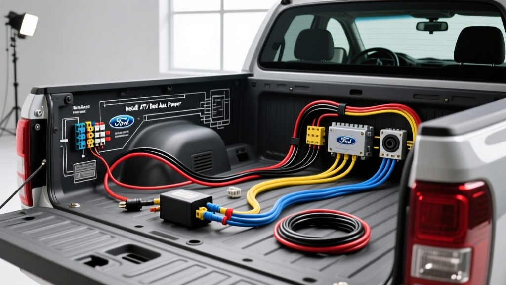
Introduction: The Need for Bed Power in ATV and UTV Hauling
Hauling your Polaris RZR, Can-Am Maverick, or Honda Pioneer in the bed of a mid-size truck requires more than just heavy-duty tie-downs. When you are staging deep in the backcountry, a dead ATV battery or the need to power a portable 12V UTV winch can quickly turn a great weekend into a logistical nightmare. Tapping into the truck's electrical system to install a high-amperage auxiliary charging point and accessory bus requires a thorough understanding of the ford ranger wiring diagram and modern vehicle power management protocols. This practical how-to guide will walk you through installing a bed-mounted Anderson SB50 power port and heavy-duty relay system, specifically tailored for ATV and UTV trail support.
Decoding the Ford Ranger Wiring Diagram for Upfitter Circuits
Modern Rangers (specifically the 2019+ T6 and T6.2 platforms) utilize a complex multiplexed electrical network managed by the Body Control Module (BCM). When consulting the Ford Body Builder Layout Book (BBLB), you will notice that direct battery connections are heavily discouraged for high-draw accessories due to parasitic drain risks. Instead, the factory provides an Upfitter Relay Block (typically located in the engine bay near the firewall or behind the passenger kick panel). By utilizing the factory upfitter switch circuits, you can trigger a high-amperage continuous duty solenoid without splicing into critical CAN-bus wiring. The ford ranger wiring diagram dictates that Upfitter Switch 1 (Aux 1) provides a 12V+ trigger signal only when the ignition is in the 'Run' position, making it the perfect signal wire for an ATV charging relay.
The Smart Alternator and BMS Challenge
The most critical hurdle in modern truck upfitting is the Battery Management System (BMS). The Ford Ranger uses a smart alternator controlled by a shunt sensor located directly on the negative battery cable. If you wire an ATV charger directly to the battery positive and ground it to the truck's chassis, the BMS shunt will not detect the current draw. Consequently, the Powertrain Control Module (PCM) will assume the battery is fully charged and drop the alternator output to 12.7V or lower to save fuel. At 12.7V, your ATV battery will not charge. To force the PCM to ramp the alternator up to 14.4V, your auxiliary ground return must be routed back to the battery negative post or the designated BMS ground lug, ensuring the shunt registers the load.
Component List and Wire Specifications
Adhering to SAE International J1128 standards for low-tension primary cable, the following components and wire gauges are required for a safe, voltage-drop-minimized installation capable of handling UTV accessory loads and ATV charging currents.
| Circuit Function | AWG Size | Wire Color (SAE) | Connector Type | Overcurrent Protection |
|---|---|---|---|---|
| Main Battery Feed to Bed | 6 AWG | Red | Ring Terminal (3/8 in) | 80A ANL Fuse |
| Solenoid Trigger (Upfitter) | 14 AWG | Blue | Deutsch DT 2-Pin | 10A ATO Blade |
| Chassis Ground Return | 6 AWG | Black | Ring Terminal (3/8 in) | N/A |
| Anderson SB50 Bed Pigtail | 8 AWG | Red/Black | SB50 Housing | Integrated |
Step-by-Step Installation Guide
Step 1: Routing the 6 AWG Feeder and Ground Return
Begin by disconnecting the negative terminal on the truck battery. Route the 6 AWG Red positive feed wire from the battery compartment, through the engine bay firewall grommet (or along the interior frame rail if avoiding the cab), and down to the rear bed crossmember. Use split-loom tubing and UV-resistant zip ties every 12 inches to protect the wire from exhaust heat and debris. Crucially, run the 6 AWG Black ground wire alongside the positive feed. Do not ground the bed system to the frame; route the Black wire all the way back to the engine bay to terminate at the battery negative post or the BMS shunt grounding point. This guarantees the smart alternator recognizes the ATV charging load.
Step 2: Wiring the Heavy-Duty Continuous Duty Solenoid
Mount a Trombetta or Cole Hersee 12V Continuous Duty Solenoid (rated for at least 150A) in a dry, ventilated area of the bed, preferably inside a weatherproof marine fuse block enclosure. Connect the 6 AWG Red wire from the battery to the solenoid's 'A' (Battery) terminal, ensuring an 80A ANL fuse is installed within 18 inches of the battery positive post. Connect the 6 AWG Black ground to the solenoid's chassis ground tab. For the trigger circuit, run a 14 AWG Blue wire from the Ford Ranger's Upfitter Switch 1 relay output to the solenoid's 'S' (Signal) terminal. When you flip the Upfitter switch on the dash, the solenoid will engage, safely sending high-amperage power to the bed without overloading the factory dash switch.
Step 3: Terminating the Anderson SB50 Connector
The Anderson Power Products SB50 is the industry standard for ATV/UTV quick-disconnects, winches, and accessory buses. Strip 5/8 inch of insulation from the 8 AWG pigtail wires. Use a dedicated Anderson hex-crimp die to compress the contacts onto the wire strands. A standard jaw crimp will deform the contact, causing it to stick inside the housing or create a high-resistance hot spot. Insert the crimped Red contact into Pin A (Positive) and the Black contact into Pin B (Negative) of the grey SB50 housing until you hear a definitive click. Apply a thin layer of dielectric grease to the contacts to prevent corrosion from trail mud and water crossings.
Troubleshooting Common Voltage Drop Issues
Even with a perfect physical installation, electrical gremlins can arise when interfacing truck power with off-road vehicles. Use the following decision tree to diagnose issues.
- Symptom: ATV battery is not charging despite 14.2V measured at the truck battery.
- Cause: BMS Shunt Grounding Error. The auxiliary ground is tied to the chassis instead of the battery negative post, bypassing the BMS shunt. The PCM drops alternator voltage to 12.7V.
Fix: Reroute the 6 AWG black ground wire directly to the battery negative terminal or the designated BMS ground lug to force the PCM to recognize the load. - Symptom: Anderson SB50 connector housing melts under heavy UTV winch loads.
- Cause: Improper crimp or stranded wire splay causing high resistance at the terminal interface.
Fix: Cut off the damaged contacts. Use a proper hex-crimp die, ensuring no copper strands escape the barrel. Verify the wire gauge matches the contact rating (e.g., using 6 AWG wire on a 8 AWG contact will cause splay). - Symptom: Solenoid clicks rapidly but does not hold closed.
- Cause: Voltage drop on the 14 AWG trigger wire due to excessive length or a poor ground on the solenoid coil.
Fix: Check the voltage at the 'S' terminal while the Upfitter switch is engaged. If it reads below 10.5V, upgrade the trigger wire to 12 AWG or ensure the solenoid mounting bracket has bare-metal contact with a cleaned chassis ground.
Alternative: Using a DC-DC Charger for Sensitive UTV Lithium Batteries
If you are charging modern UTVs equipped with Lithium-Iron-Phosphate (LiFePO4) batteries, a simple solenoid relay is insufficient and potentially dangerous. Lithium batteries require specific multi-stage charging profiles and will draw massive, unregulated current from the Ranger's alternator, potentially tripping the truck's factory protection circuits. In this scenario, bypass the solenoid and install a 20A or 40A DC-DC charger (such as a Redarc or Victron unit) in the bed. Wire the DC-DC charger's ignition sense wire to the Upfitter circuit, and connect the heavy-gauge input directly to the battery and BMS ground. This ensures your off-road vehicles receive a safe, regulated charge while preserving the integrity of the Ford Ranger's electrical architecture.