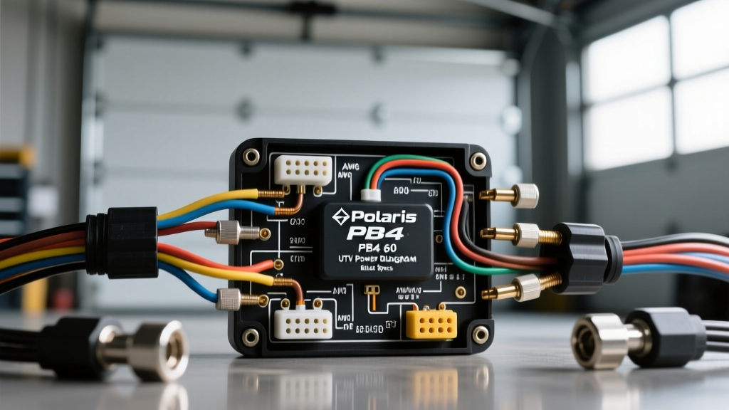
Overview of the Polaris PB4 60 Power Distribution Block
The Polaris PB4 60 is a high-capacity, 4-post power distribution block (bus bar) engineered specifically for the rigorous electrical demands of modern off-road vehicles, including the Polaris RZR Pro XP, Ranger 1000, and General 1000 platforms. Rated for 60 amps continuous duty per post (with a total block capacity governed by the main feed cable), the PB4 60 serves as the central nexus for high-draw aftermarket accessories such as winches, HID/LED light bars, and auxiliary cooling fans. Understanding the precise Polaris PB4 60 wiring diagram is critical for preventing voltage drop, thermal runaway, and catastrophic electrical fires in high-vibration UTV environments.
Unlike standard automotive relay blocks, the PB4 60 utilizes solid copper bus bars with tin-plated M8 stainless steel studs to resist galvanic corrosion and maintain low millivolt drop across connections. This technical specification reference details the exact pinout configurations, AWG matrices, torque values, and routing protocols required for a factory-grade installation.
PB4 60 Terminal Pinout & Wiring Diagram Layout
The physical layout of the PB4 60 block features four isolated M8 stud terminals encased in a glass-reinforced nylon (PA66-GF30) housing. This material provides high dielectric strength and resistance to UV degradation and automotive fluids. Below is the standard wiring diagram pinout reference for integrating the PB4 60 into a Polaris UTV electrical system.
| Terminal ID | Function | Recommended Wire Color | Source / Destination | Max Continuous Draw |
|---|---|---|---|---|
| Post 1 (Main In) | Primary 12V+ Feed | Red (SAE J1128) | Direct to Battery Positive via Mega Fuse | 60A (Block Limit) |
| Post 2 (Switched) | Ignition-Switched 12V+ | Yellow / Red Tracer | Polaris Accessory Bus (Keyed Power) | 15A (Relay Trigger) |
| Post 3 (Aux 1) | High-Draw Accessory 1 | Blue | Winch Contactor / Light Bar Relay | 30A |
| Post 4 (Aux 2) | High-Draw Accessory 2 | Green | Auxiliary Fuel Pump / Cooling Fan | 30A |
Diagram Note: The main ground return for all accessories must NOT be routed back through the PB4 60. The PB4 60 is a positive-only distribution node. All accessory grounds must be terminated at the vehicle chassis or a dedicated negative bus bar tied directly to the battery negative terminal using a minimum 6 AWG cable.
Wire Gauge (AWG) & Amperage Capacity Matrix
When executing the Polaris PB4 60 wiring diagram, selecting the correct American Wire Gauge (AWG) is non-negotiable. Off-road vehicles operate in high-ambient-temperature environments, often exceeding 120°F (49°C) near the engine bay and exhaust routing. Therefore, wire ampacity must be derated according to SAE J1128 standards for low-tension primary cable and battery wire.
| Wire Size (AWG) | Stranding Count | Max Amps (Engine Bay / 120°F) | Max Amps (Cabin / 80°F) | Application on PB4 60 |
|---|---|---|---|---|
| 4 AWG | 1332 | 120A | 160A | Post 1 Main Feed (Short Runs) |
| 6 AWG | 1064 | 80A | 120A | Post 1 Main Feed (Runs > 5 ft) |
| 10 AWG | 266 | 30A | 45A | Posts 3 & 4 (Light Bars, Fans) |
| 12 AWG | 168 | 20A | 30A | Post 2 (Relay Coil Triggers) |
Technical Insight: Never use Copper-Clad Aluminum (CCA) wire for UTV applications. CCA wire exhibits a 40% higher electrical resistance than pure OFC (Oxygen-Free Copper) and is highly susceptible to galvanic corrosion when mated to the tin-plated M8 studs of the PB4 60 block. Always specify SAE J378 or SAE J1128 compliant pure copper stranded wire.
Crimping Methodologies & Termination Standards
The number one cause of failure in UTV power block installations is improper terminal crimping. The vibration profile of a Polaris RZR or Ranger traversing whoops and washboards will rapidly fatigue and fracture a poorly executed crimp, leading to increased resistance and localized melting.
- Hex Crimp vs. Indent Crimp: For the 4 AWG and 6 AWG main feed cables terminating at Post 1, a closed-barrel hex crimp is mandatory. Hex crimping applies uniform 360-degree radial compression, cold-welding the copper strands to the terminal barrel and eliminating internal air pockets where moisture could initiate oxidation.
- Adhesive-Lined Heat Shrink: All terminals must be sealed with dual-wall, adhesive-lined polyolefin heat shrink (3M MDT or equivalent). When heated, the inner thermoplastic layer melts and flows into the wire interstices, creating a waterproof barrier that prevents capillary action from drawing moisture into the wire strands.
- Anti-Oxidant Paste: Apply a thin layer of conductive anti-oxidant compound (e.g., Noalox or OxGard) to the tinned surface of the terminal ring before mating it to the PB4 60 copper bus bar. This breaks down surface oxides under torque pressure and prevents future galvanic corrosion.
Torque Specifications & Hardware Requirements
Overtightening the M8 studs on the PB4 60 block can strip the internal threads of the copper bus bar, while undertightening allows micro-movements that cause fretting corrosion and thermal runaway. Adhere strictly to the following hardware and torque specifications:
- Hardware: Use only 316-grade stainless steel M8 x 1.25 hex nuts and flat washers. Never use zinc-plated steel hardware, as the dissimilar metals (zinc, copper, tin) in the presence of moisture will create a galvanic cell, rapidly corroding the bus bar.
- Washer Stackup: The correct stackup from the stud base upward is: Terminal Ring -> Flat Washer (to distribute load) -> Split Lock Washer or Nord-Lock wedge-locking washer -> Hex Nut.
- Torque Value: Torque all M8 terminal nuts to 10 Nm (88.5 in-lbs). Use a calibrated inch-pound torque wrench. Do not guess or use a standard ratchet, as the leverage can easily exceed the yield strength of the M8 stud.
UTV Routing Paths & Environmental Protection
When routing cables from the PB4 60 block to the battery and accessories, environmental hazards must be mitigated. Polaris UTVs feature tight chassis tolerances, and improper routing frequently results in chafed insulation and dead shorts.
Exhaust and Heat Shield Clearances
Maintain a minimum clearance of 6 inches (15 cm) between any wiring harness and the exhaust header or catalytic converter. If routing near the firewall or underbody where clearance is restricted, the wiring must be encased in high-temperature fiberglass sleeving (rated to 1000°F) or corrugated nylon loom secured with high-temp P-clamps.
Chassis Penetration and Grommets
When passing the main 6 AWG feed cable through the Polaris firewall or bulkhead, always utilize a stepped rubber grommet. Apply dielectric grease to the cable before pulling it through the grommet to reduce friction and prevent the insulation from tearing on the stamped steel chassis edges.
Diagnostic Testing & Common Failure Modes
Even with a flawless installation, the PB4 60 block should be subjected to baseline diagnostic testing to ensure optimal conductivity. Use a digital multimeter (DMM) capable of measuring millivolts (mV) to perform a Voltage Drop Test across the block.
- Set the DMM to the DC millivolt scale.
- Place the red probe on the battery positive terminal and the black probe on Post 1 of the PB4 60.
- Activate a high-draw load (e.g., engage the winch or turn on a 200W light bar).
- Acceptable Threshold: The voltage drop across any single connection or cable run should not exceed 0.1V (100mV). A reading above 0.2V indicates high resistance, typically caused by a loose crimp, insufficient torque, or internal strand corrosion.
Thermal Runaway Failure Mode: If a terminal nut vibrates loose, the contact area decreases, causing resistance to spike. According to Joule's Law (P = I²R), this increased resistance generates intense localized heat. This heat expands the metal, further loosening the nut, creating a destructive feedback loop that will melt the PA66-GF30 housing and ignite surrounding debris. Implementing Nord-Lock washers and periodic post-ride torque checks eliminates this failure mode.
Authoritative References
- SAE International - J1128: Low Tension Primary Cable Standard: Defines the thermal and electrical requirements for automotive battery and primary wiring used in UTV power block feeds.
- Blue Sea Systems Engineering Resources: Industry-standard guidelines for bus bar sizing, stud torque specifications, and marine/off-road environmental protection protocols.
- Polaris Off-Road Owner's Manuals & Service Documentation: Reference for factory chassis grounding points, accessory bus keyed-power limits, and OEM wiring color codes for Ranger and RZR platforms.