Introduction to Aftermarket Switchgear
When executing an upgrade and modification project on a truck, Jeep, or overland rig, the rocker switch is the critical interface between the driver and high-draw auxiliary systems. Whether you are wiring a 40-inch LED light bar, an onboard air compressor, or a heavy-duty winch solenoid, understanding how a rocker switch works internally is the difference between a reliable, factory-style dash integration and a melted wiring harness. While they appear simple on the surface, automotive-grade rocker switches are complex electromechanical devices engineered to handle high-current DC loads, resist moisture ingress, and manage the unique challenges of 12V automotive electrical systems.
How Does a Rocker Switch Work Internally?
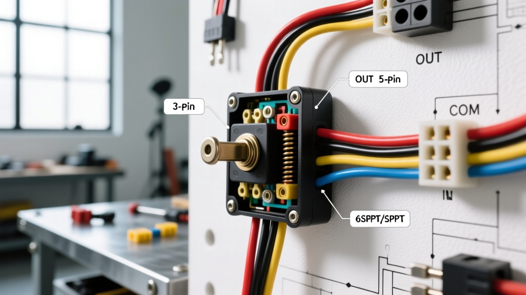
To answer the core question—how does a rocker switch work?—we must look past the ABS plastic actuator and examine the internal contact mechanics. When you press the top of the rocker actuator, it pivots on a central fulcrum. This seesaw motion pushes a spring-loaded plunger downward. The plunger forces a movable contactor (often a copper alloy wiper) to bridge the gap between the stationary input and output terminals.
In high-quality automotive switches, such as those manufactured by Carling or Littelfuse, the contact surfaces are not bare copper. They are coated with Silver Tin Oxide (AgSnO2) or Silver Cadmium Oxide (AgCdO). This specific metallurgy is vital for 12V DC applications because DC current does not have a natural zero-crossing point like AC current, meaning electrical arcs can persist and pit the contacts. The oxide coating provides superior arc suppression and thermal conductivity, ensuring the switch can handle its rated 20A continuous load without experiencing thermal runaway.
The housing is typically molded from high-temperature Nylon or ABS, designed to withstand the ambient heat of a crowded engine bay or the direct UV exposure of a dash-mounted pod. The external connections rely on standard 0.250-inch (6.35mm) FASTON spade terminals, which require fully insulated, crimped female disconnect connectors to prevent short circuits against the metal dash bezel.
Decoding the Pins: SPST vs. SPDT Configurations
Custom wiring projects generally utilize Single Pole Single Throw (SPST) or Single Pole Double Throw (SPDT) configurations. The number of pins on the back of the switch dictates its functionality, particularly regarding illumination logic. Below is the standard pinout for the most common aftermarket 5-pin SPST rocker switch (ON-OFF) used in off-road modifications.
| Terminal / Pin | Standard Function | Wire Gauge (AWG) | Connection Destination |
|---|---|---|---|
| Pin 1 (Top) | 12V+ Source Input | 16 AWG TXL | Fused 12V+ ignition or battery bus |
| Pin 2 (Middle) | Load Output | 16 AWG TXL | Relay Coil (Pin 86) or direct low-draw load |
| Pin 3 (Bottom) | Normally Closed (NC) | N/A | Unused in standard ON-OFF SPST mods |
| Pin 4 (Inner) | Illumination 12V+ | 18 AWG GXL | Dash dimmer circuit or secondary ignition source |
| Pin 5 (Inner) | Illumination Ground | 18 AWG GXL | Chassis ground or dedicated ground bus bar |
Note: Pin numbering on generic imported switches can vary. Always verify continuity with a digital multimeter (DMM) before applying power. A reliable reference for switch schematics is the Littelfuse Rocker Switch Catalog, which details exact internal circuit maps for commercial vehicle applications.
Illumination Logic: Dependent vs. Independent Circuits
A major aspect of how a rocker switch works involves its internal illumination circuit, which operates entirely independently of the load circuit in a 5-pin setup. This is known as 'independent illumination.' Pin 1 and Pin 2 handle the high-current load switching, while Pins 4 and 5 power the internal LED or neon lamp.
If you are using modern LED-illuminated rocker switches, polarity matters. LEDs are diodes; if you reverse the 12V+ and Ground on Pins 4 and 5, the switch will still mechanically function and pass current to your relay, but the LED will not illuminate. Conversely, older incandescent or neon-illuminated switches are non-polarized. Furthermore, if you wire Pin 4 to a variable dash dimmer circuit (PWM or variable resistance), ensure the switch utilizes an incandescent bulb or a PWM-compatible LED driver; standard LEDs will flicker violently or fail prematurely when subjected to aftermarket dimmer rheostats.
Upgrade Project: Wiring a 5-Pin Rocker for an Air Compressor
Let us apply this knowledge to a real-world modification: wiring a dash-mounted rocker switch to control a 12V onboard air compressor (e.g., ARB Twin or VIAIR 400P) via a 40A Bosch-style automotive relay. Never run a high-draw compressor directly through the rocker switch contacts; the inrush current will instantly weld the AgSnO2 contacts together, causing the switch to fail in the 'ON' position.
- Prepare the Control Circuit: Run a 16 AWG TXL wire from a fused 12V+ ignition source to Pin 1 on the rocker switch.
- Wire the Output: Connect a 16 AWG wire from Pin 2 to Pin 86 on your 40A relay. This wire only carries the relay coil draw (typically less than 150mA).
- Complete the Relay Coil Ground: Run a 16 AWG wire from Relay Pin 85 to a clean, bare-metal chassis ground.
- Wire the Illumination: Connect 18 AWG GXL wire from your dash illumination circuit to Pin 4, and ground Pin 5. This ensures the switch only lights up when your headlights or parking lights are on.
- Route the High-Current Load: Run 10 AWG SGX wire from the battery positive terminal (via a 40A MAXI fuse) to Relay Pin 30. Run another 10 AWG wire from Relay Pin 87 directly to the compressor's positive terminal.
By utilizing this relay-isolated topology, the rocker switch only manages a fraction of an amp, vastly extending its mechanical lifespan while allowing the heavy-gauge wiring to handle the compressor's 30A+ continuous draw. For comprehensive relay integration guidelines, refer to the Painless Performance Wiring Manuals.
Inductive Kickback and Arc Suppression
When modifying vehicles with inductive loads like winch solenoids, fuel pumps, or compressor clutches, you must account for inductive kickback. When the rocker switch is flipped to the 'OFF' position, the collapsing magnetic field in the relay coil or motor generates a high-voltage reverse spike. Over time, this spike will cause micro-arcing across the switch's internal contacts, leading to carbon buildup and increased electrical resistance.
To mitigate this in advanced custom builds, wire a 1N4007 flyback diode in reverse parallel across the relay coil (Pins 85 and 86). The cathode (stripe) faces the 12V+ side. This provides a safe recirculation path for the voltage spike, protecting both the rocker switch contacts and sensitive CAN-bus modules from electromagnetic interference (EMI).
Troubleshooting Common Mod Failures
Even with proper wiring, environmental factors in off-road builds can cause switch failures. Here is a diagnostic decision tree for common issues:
- Symptom: Switch feels 'mushy' and load drops out over bumps.
Cause: Moisture ingress has caused galvanic corrosion on the internal copper wiper, increasing contact resistance and generating excess heat, which softens the ABS housing.
Fix: Replace the switch with an IP68-rated marine-grade unit (e.g., Blue Sea Systems) and apply dielectric grease to the 0.250-inch FASTON terminals. - Symptom: LED illumination flickers when the engine is off.
Cause: Parasitic draw or backfeed from a CAN-bus monitored lighting circuit.
Fix: Install a 10k-ohm pull-down resistor between Pin 2 (Output) and ground to bleed off residual capacitance. - Symptom: Voltage drop across the switch exceeds 0.2V under load.
Cause: Pitted AgSnO2 contacts from switching an inductive load without a relay.
Fix: Verify the load is routed through a relay. If the switch is directly powering a 5A accessory, replace the switch and verify the crimp quality on the spade connectors using a wire-pull test.
Mastering how a rocker switch works is foundational to any custom automotive electrical project. By respecting contact metallurgy, isolating high-current loads with relays, and properly managing independent illumination circuits, you ensure your aftermarket accessories operate flawlessly in the harshest environments.