Automotive Rocker Switch Topologies and Contact Ratings
When designing auxiliary electrical systems for off-road vehicles, marine applications, or custom overland builds, the humble rocker switch serves as the primary human-machine interface. However, treating all rocker switches as simple single-pole, single-throw (SPST) on/off toggles is a critical engineering mistake. Advanced custom installations require a deep understanding of switch topologies, internal LED illumination schematics, and the electromechanical realities of driving inductive loads like relays and DC motors.
Most high-quality automotive rocker switches (such as those conforming to the VXR/Carling V-Series contour footprint) utilize silver cadmium oxide (AgCdO) contacts. These contacts are specifically designed to resist welding under high inrush currents. While a switch may be rated for 20A at 12VDC steady-state, the inrush current of a halogen light bar or a DC winch motor can easily exceed 40A for the first 50 milliseconds. Understanding the difference between SPDT (Single Pole, Double Throw) and DPDT (Double Pole, Double Throw) configurations is essential for complex circuit routing, polarity reversal, and multi-stage accessory control.
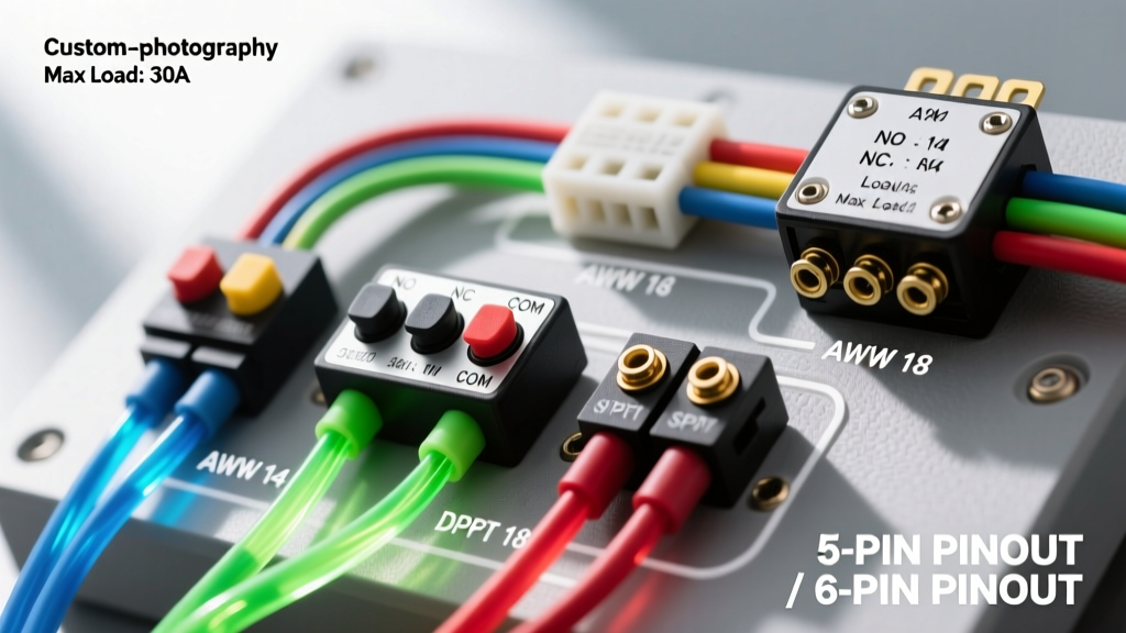
Standard 5-Pin SPDT Rocker Switch Pinout & Internal Schematic
The 5-pin SPDT (ON-ON or ON-OFF-ON) rocker switch is the workhorse of dual-circuit accessory management. It is commonly used to switch between two different auxiliary light bars, select between dual-speed cooling fans, or toggle between a primary and secondary fuel pump. Below is the industry-standard terminal map for a 5-pin illuminated SPDT switch.
| Terminal Pin | Function | Circuit Role | Recommended Wire Color (SAE) |
|---|---|---|---|
| Pin 2 | Common (Input) | Main 12V+ Power Feed (Fused) | Red (12 AWG) |
| Pin 3 | Throw 1 (Output A) | Load 1 or Relay Coil A | Blue (18 AWG) |
| Pin 5 | Throw 2 (Output B) | Load 2 or Relay Coil B | Green (18 AWG) |
| Pin 1 | LED Anode (+) | Illumination Power (Ignition or Dash Dimmer) | White (18 AWG) |
| Pin 4 | LED Cathode (-) | Illumination Ground | Black (18 AWG) |
Expert Note on Illumination: In dependent-ground switches, the internal LED only illuminates when the switch is actuated and power flows to the load. In independent-ground switches (detailed above with dedicated Pins 1 and 4), the LED circuit is completely isolated from the switching circuit. This allows you to wire Pin 1 to a dash-light dimmer circuit (often a 12V PWM signal in modern CAN-bus vehicles) while Pin 2 receives constant battery power, ensuring the switch glows softly at night even when the accessory is turned off.
6-Pin DPDT Configurations for Polarity Reversal (Winches & Actuators)
The 6-pin DPDT (ON-OFF-ON) rocker switch is mandatory for controlling linear actuators, power windows, and portable winches where motor polarity must be reversed to change direction. This is achieved through an internal crossover bridge that swaps the positive and negative feeds to the load depending on the paddle position.
The H-Bridge Crossover Wiring Method
To wire a 6-pin DPDT switch for polarity reversal without using external relays, you must utilize the center pins as your primary power inputs and the outer pins as your crossed outputs.
- Power Inputs: Connect your main fused +12V source to Pin 2 and your main chassis Ground to Pin 5.
- Motor Connections: Run two wires directly to your DC motor or actuator. Let's call them Motor Wire A and Motor Wire B.
- The Crossover Jumpers:
- Install a jumper wire between Pin 1 and Pin 6. Connect Motor Wire A to this junction.
- Install a jumper wire between Pin 3 and Pin 4. Connect Motor Wire B to this junction.
Operational Logic: When you toggle the switch UP, Pin 2 connects to Pin 1 (+12V), and Pin 5 connects to Pin 4 (Ground). Motor A receives positive, Motor B receives negative. When you toggle DOWN, Pin 2 connects to Pin 3 (+12V), and Pin 5 connects to Pin 6 (Ground). Motor B now receives positive, and Motor A receives negative, instantly reversing the motor's rotation. For detailed mechanical and electrical tolerances of these switch mechanisms, refer to the Littelfuse Automotive Rocker Switch Datasheets.
Integrating Rocker Switches with Bosch-Style Relays
Never route high-amperage loads (anything exceeding 10A continuous, such as LED light bars, air compressors, or cooling fans) directly through the internal contacts of a dashboard-mounted rocker switch. The wire harness running through the firewall and under the dash should only carry the low-current signal required to trigger an ISO mini relay (Bosch-style 4-pin or 5-pin).
Calculating Coil vs. Load Current
A standard ISO mini relay coil (Pins 85 and 86) draws approximately 150mA to 200mA at 12VDC. This means the switch leg from your rocker switch (Pin 3) to the relay coil can safely be wired with 18 AWG or even 20 AWG primary wire, minimizing harness bulk behind the dash panel. The heavy load current (e.g., 30A for a light bar) is routed exclusively through the relay's Pin 30 (Battery +) and Pin 87 (Load Output) using appropriately sized 10 AWG or 12 AWG wire.
The Inductive Kickback Problem (Critical Failure Mode)
One of the most common, yet poorly understood, failure modes in custom automotive wiring is the destruction of the rocker switch's internal LED resistor. A relay coil is an inductor. According to Lenz's Law, when the rocker switch opens and cuts power to Pin 86 of the relay, the collapsing magnetic field generates a massive reverse-voltage spike (often exceeding 100V). This back-EMF spike travels backward through the switch leg and strikes the internal LED circuit of the rocker switch, instantly vaporizing the microscopic current-limiting resistor.
The Engineering Fix: You must install a flyback diode (such as a 1N4007) across the relay coil terminals. Solder the diode with the cathode (the silver stripe) facing the +12V switch input (Pin 86) and the anode facing the ground (Pin 85). This creates a safe recirculation loop for the inductive spike, clamping the voltage to a safe ~0.7V and saving your switch's illumination circuit. Alternatively, purchase high-end relays from Bosch Automotive Relay Specifications that feature internal suppression resistors or diodes pre-installed.
Wire Gauge (AWG) and Overcurrent Protection Sizing
Adhering to the SAE J1128 Low Tension Primary Cable Standard is non-negotiable for automotive environments, where ambient engine bay temperatures can exceed 125°C and voltage drop over long chassis runs can severely degrade accessory performance. Below is a reference chart for sizing the switch legs and load circuits commonly paired with rocker switch panels.
| Circuit Type | Max Current | Min. Wire Gauge (AWG) | Fuse Rating (ATO/ATC) | Terminal Type |
|---|---|---|---|---|
| Switch Leg (Relay Coil) | 2A | 18 AWG | 2A or 3A | #10 Ring / 0.250" Spade |
| LED Illumination Feed | 1A | 20 AWG | 1A or 2A | 0.187" Spade |
| Light Bar Load (Relay 87) | 20A | 12 AWG | 20A | 0.250" Spade / 6mm Ring |
| Winch Contactor Trigger | 5A | 14 AWG | 5A | 0.250" Spade |
| Main Battery Feed (Relay 30) | 40A | 10 AWG | 40A Maxi-Fuse | 8mm Ring / 0.375" Ring |
Environmental Sealing and Termination Best Practices
For exterior-mounted switch panels (such as those on a Jeep Wrangler cowl or a marine center console), IP65 is insufficient. You must specify IP68-rated rocker switches, which feature silicone boots and epoxy-potted internal cavities to prevent saltwater intrusion and condensation-induced short circuits.
Furthermore, never rely on bare wire pushed directly into the spade terminals of a rocker switch. The vibration profile of a vehicle will cause the strands to fray, leading to high-resistance connections, localized melting of the ABS switch housing, and eventual arcing. Always use closed-end, nylon-insulated wire ferrules or fully insulated female disconnect crimps (rated for the specific tab width, usually 0.250" or 6.35mm). Apply a dual-wall adhesive-lined heat shrink over the crimp barrel to seal out moisture and provide mechanical strain relief, ensuring a lifetime of reliable actuation in the harshest automotive environments.