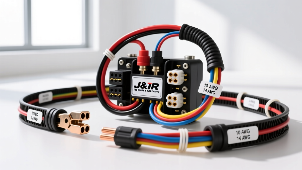
The J & R Tire Service & Auto Electric Diagnostic Standard
When diagnosing a no-crank condition or upgrading a vehicle's charging system, the difference between a parts-changer and a true auto electrical expert lies in the methodology. The protocols established by J & R Tire Service & Auto Electric represent a benchmark in the industry for rigorous, physics-based electrical diagnostics. Rather than simply swapping starters and alternators based on age, this walkthrough dissects the complete wiring architecture of the starting and charging circuits. By understanding the exact path of electron flow, voltage drop thresholds, and terminal pin configurations, technicians can eliminate parasitic draws, prevent ignition switch burnout, and ensure peak cranking amperage delivery.
In this comprehensive wiring diagram walkthrough, we will explore the high-current starter architecture, the low-current ignition control circuit, and the critical integration of the GM Delco CS130/CS144 alternator 4-pin connector. Whether you are restoring a classic muscle car or troubleshooting a late-model light-duty truck, these J & R Tire Service & Auto Electric protocols will ensure your wiring is robust, safe, and compliant with SAE standards.
High-Current Starter Architecture: Battery to Solenoid
The foundation of any starting system is the high-current path from the battery positive terminal to the starter solenoid 'B+' (Battery) stud. During engine cranking, a standard V8 engine can demand between 150 to 250 amps, while high-compression or diesel applications can easily exceed 400 amps. The J & R Tire Service & Auto Electric methodology dictates that voltage drop on this positive cable must never exceed 0.5 volts under maximum cranking load.
Cable Selection and Terminal Preparation
Many aftermarket repair manuals incorrectly suggest using standard stranded copper wire for starter feeds. However, true automotive electrical best practices require the use of SAE J1128 compliant welding cable or specifically rated primary battery cable. The fine stranding of welding cable provides superior flexibility and vibration resistance, preventing the internal copper fractures that lead to high-resistance hot spots.
- Wire Gauge: Minimum 1/0 AWG for standard V8 applications; 2/0 AWG or 3/0 AWG for diesel or high-compression engines exceeding 300 amps.
- Terminals: Use heavy-duty, thick-wall copper ring terminals (e.g., 3/8' inner diameter for standard GM Delco starters). Avoid thin-wall brass or aluminum terminals, which gall and loosen under thermal cycling.
- Crimping & Sealing: Terminals must be applied using a hydraulic hex-indent crimper. Dot-indent crimpers often leave voids in the wire barrel. Following the crimp, the connection must be sealed with dual-wall, adhesive-lined polyolefin heat shrink. The inner adhesive layer melts and flows into the wire strands, preventing capillary action from drawing battery acid and moisture up into the copper strands, which causes the dreaded 'green crust' corrosion.
When securing the B+ cable to the starter solenoid stud, torque specifications are critical. Over-torquing can strip the soft copper stud or crack the internal bakelite insulator, causing a dead short to the starter housing. The standard torque for a 3/8'-16 starter stud is typically 89 to 106 lb-in (10 to 12 Nm). Always use a flat washer and a split lock washer or a flange nut to maintain clamp load under extreme engine vibration.
The Control Circuit: Ignition, NSS, and Solenoid 'S' Terminal
While the B+ cable handles the heavy lifting, the control circuit is responsible for actuating the solenoid plunger. In a standard GM or Ford configuration, turning the ignition key to the 'START' position sends 12V+ through the Neutral Safety Switch (NSS) or clutch interlock switch, and finally to the 'S' (Start) terminal on the starter solenoid.
A common failure mode identified in J & R Tire Service & Auto Electric case studies is the melting of the ignition switch harness connector. Starter solenoids require an initial pull-in current of 15 to 30 amps to overcome the solenoid spring and engage the drive pinion. Routing this inductive spike directly through the dashboard ignition switch and thin 14 AWG factory wiring inevitably leads to voltage drop and melted plastic connectors.
The Starter Relay Upgrade Protocol
To protect the ignition switch and ensure maximum voltage reaches the solenoid, a heavy-duty starter relay (such as a standard Bosch-style 30A/40A SPDT relay) should be integrated into the control circuit.
- Pin 86 (Coil +): Connect to the original ignition 'START' wire (usually 12 AWG Purple or Yellow).
- Pin 85 (Coil -): Connect to a clean, bare-metal chassis ground.
- Pin 30 (Common): Connect directly to the Battery Positive terminal via an inline 30A fuse and 10 AWG wire.
- Pin 87 (Normally Open): Connect to the starter solenoid 'S' terminal using 12 AWG wire.
This configuration ensures that the ignition switch only carries the minimal 0.2A current required to energize the relay coil, while the relay contacts deliver a full, unimpeded 12V+ directly from the battery to the solenoid, resulting in significantly faster and more authoritative engine cranking.
Alternator Integration: The GM CS130/CS144 4-Pin Connector
No wiring walkthrough is complete without addressing the charging system. The GM CS130 and CS144 internally regulated alternators are staples in the automotive electrical world, yet they are frequently miswired by amateur mechanics. The Delphi Weather-Pack 4-pin connector dictates the alternator's voltage regulation and excitation. Misinterpreting these pins leads to overcharging, undercharging, or complete diode bridge failure.
For deeper technical reference on GM alternator wiring, the Mad Electrical Alternator Tech Guide provides excellent schematic validation.
| Terminal | Function | Wire Color (Typical) | AWG | Routing Destination |
|---|---|---|---|---|
| L | Lamp / Exciter | Brown/White | 12 | Ignition Switch / Dash Warning Lamp |
| F | Field PWM | Gray | 18 | PCM / ECM (Duty Cycle Signal) |
| S | Sense | Red | 12 | Battery Positive / Main Junction Block |
| P | Phase / Stator | Purple | 18 | Tachometer / Electric Choke Relay |
Critical Wiring Rules for the CS Series
The 'S' (Sense) Terminal Rule: The most common catastrophic wiring error is jumping the 'S' terminal directly to the alternator's B+ output stud. The 'S' terminal is designed to read the actual voltage at the battery or main electrical distribution block. If jumped at the alternator, the regulator will compensate only for the voltage at the alternator case, ignoring the 0.5V to 1.0V drop occurring across the main B+ charge cable. This results in the battery chronically undercharging, leading to sulfation and premature failure. The 'S' wire must be routed independently back to the battery positive terminal or the main firewall junction block.
The 'L' (Lamp) Terminal Excitation: The internal voltage regulator requires a small initial current to 'turn on' or excite the rotor field. This is provided via the 'L' terminal through the dashboard 'GEN' or 'ALT' warning bulb. If the vehicle uses an LED dash indicator (which draws negligible current) or if the bulb burns out, the alternator will not excite and will output 0 volts. To prevent this, a 56-ohm, 1/2-watt resistor must be wired in parallel with the dash bulb to guarantee a minimum excitation current path, a standard fix championed by J & R Tire Service & Auto Electric technicians.
J & R Tire Service & Auto Electric Voltage Drop Protocol
A multimeter reading 12.6V at the battery with the key off tells you nothing about the health of the wiring under load. The definitive test for any starting or charging circuit is the Voltage Drop Test. According to the SAE J1128 Low Tension Primary Cable Standard and general automotive diagnostic best practices, voltage drop must be measured while the circuit is actively under load (cranking or charging).
Step-by-Step Cranking Voltage Drop Test
- Disable Ignition/Fuel: Pull the fuel pump relay or disable the ignition coils to allow the engine to crank continuously without starting.
- Set DMM: Set your Digital Multimeter to DC Volts (Auto-ranging or 2V scale).
- Positive Side Drop: Place the red probe on the Battery Positive Post (not the clamp, the actual lead post) and the black probe on the Starter Solenoid B+ Stud. Crank the engine. A reading above 0.5V indicates excessive resistance in the positive cable, terminals, or battery clamps.
- Negative Side Drop: Place the red probe on the Starter Housing (bare metal) and the black probe on the Battery Negative Post. Crank the engine. A reading above 0.2V indicates poor engine-to-chassis grounding or corroded negative battery cables.
By isolating the circuit into positive and negative halves, technicians can pinpoint exactly where energy is being lost as heat, avoiding the unnecessary replacement of perfectly good starter motors.
SAE J1128 Wire Gauge (AWG) Specification Chart
Selecting the correct wire gauge is non-negotiable in auto electrical work. Undersized wires act as resistors, generating heat and reducing voltage at the component. The following chart outlines the J & R Tire Service & Auto Electric standard for wire sizing based on SAE J1128 high-temperature primary cable ratings.
| AWG Size | Max Amperage (SAE J1128) | Typical Application | Terminal Type |
|---|---|---|---|
| 1/0 | 150A - 260A | Battery to Starter Solenoid B+ | 3/8' Ring, Adhesive Heat Shrink |
| 2 | 120A - 200A | High-Output Alternator B+ to Battery | 5/16' Ring, Adhesive Heat Shrink |
| 4 | 80A - 120A | Standard Alternator B+ / Winch Power | 5/16' Ring, Adhesive Heat Shrink |
| 8 | 40A - 60A | Heavy Duty Accessory Relays (e.g., Fans) | #10 Stud Ring |
| 10 | 25A - 35A | Headlight Relays, Fuel Pump Feeds | Weather-Pack / Ring |
| 12 | 15A - 20A | Ignition Control, Solenoid 'S' Terminal | Weather-Pack / Spade |
| 14 | 10A - 15A | Interior Lighting, ECU Sensors | Weather-Pack / Deutsch DT |
Conclusion
Automotive electrical systems are unforgiving of poor workmanship. A loose crimp, an incorrectly routed sense wire, or an undersized ground cable will inevitably lead to stranded vehicles and damaged components. By adopting the J & R Tire Service & Auto Electric wiring walkthrough protocols—prioritizing adhesive-lined heat shrink, utilizing starter relays to protect ignition switches, correctly wiring the CS130/144 4-pin connector, and religiously performing voltage drop tests—technicians can build and repair electrical systems that are as reliable as they are efficient. Always consult factory wiring diagrams and verify pinouts with a multimeter before applying power to any newly constructed harness.