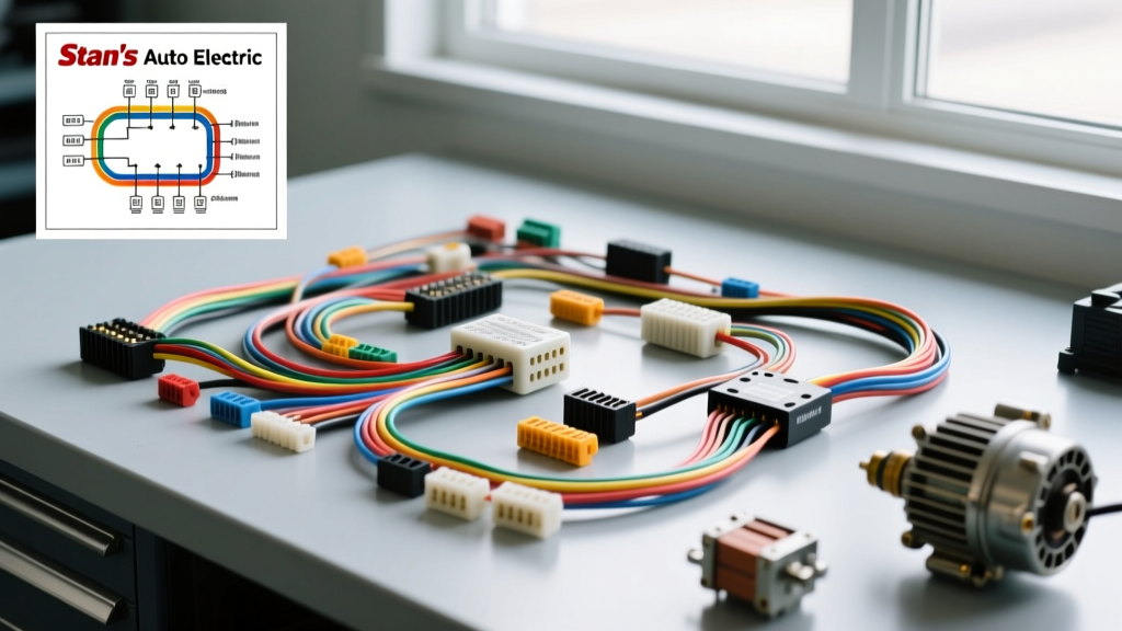
The Philosophy of Custom Classic Harness Architecture
When restoring a classic muscle car or vintage truck, the factory wiring harness is often the weakest link. Original equipment manufacturer (OEM) harnesses from the 1960s and 1970s were designed for minimal electrical loads: points-style ignitions, low-output alternators, and incandescent lighting. Today's restorations demand high-output ignition systems, electric fuel pumps, and modern audio. The 'Stan's Auto Electric' methodology—a benchmark in the custom restoration community—focuses on circuit isolation, heavy-gauge power distribution, and relay-driven high-draw accessories. This complete wiring diagram walkthrough breaks down the architecture of a modernized classic harness, providing actionable specifications, wire color codes, and bulkhead pinouts for your next build.
Upgrading Core Power Distribution & Alternator Circuits
The foundation of any Stan's Auto Electric style harness is the main power feed. Factory harnesses often routed 12 AWG or 14 AWG wires from a low-amperage generator or early 10SI alternator directly to the ammeter and then to the firewall. This creates a massive fire hazard and severe voltage drop when upgrading to a modern 12SI, 14SI, or 100-amp+ CS130 alternator.
In a proper custom harness, the ammeter is deleted in favor of a high-quality voltmeter, and the main charge wire is upgraded. According to SAE J1128 Low Tension Primary Cable standards, wire ampacity drops significantly in high-temperature engine bays. For a 100-amp alternator, the charge wire running from the alternator BAT terminal to the starter solenoid or main battery junction must be a minimum of 8 AWG (preferably 6 AWG for runs exceeding 6 feet).
- Main Charge Wire: 8 AWG Red, ring terminal crimped with an open-barrel press, sealed with 3M heat-shrink tubing.
- Exciter Wire (Terminal 1 on 10SI/12SI): 14 AWG Brown, routed to the dash idiot light, featuring an inline 10-ohm, 2-watt resistor if converting to an LED dash bulb to ensure proper alternator excitation.
- Voltage Sense Wire (Terminal 2): 14 AWG Red, routed directly to the main battery positive terminal or the ignition switch BAT post to ensure the regulator reads true system voltage, not the voltage drop across the firewall bulkhead.
The Headlight Relay Upgrade (Eliminating Voltage Drop)
Factory headlight circuits routed full headlight amperage (often 12-15 amps) through the firewall, into the cabin, through the headlight switch, and back out to the front of the car. This 20-foot round trip on 14 AWG wire results in a severe voltage drop, leaving modern halogen or LED headlights dim. The Stan's Auto Electric approach utilizes Bosch-style 30A SPDT relays mounted in the engine bay, directly fed by the battery.
The headlight switch now only carries the low-amperage coil trigger current (under 1 amp) for the relays. Below is the standard relay pinout configuration for the high and low beam circuits:
- Pin 30 (Power In): 10 AWG Red wire from the battery junction block, protected by a 30A MAXI fuse.
- Pin 87 (Normally Open Output): 12 AWG Green (Right) and 12 AWG Tan (Left) wires routing to the headlight buckets.
- Pin 85 (Coil Ground): 14 AWG Black wire tied to a dedicated radiator support chassis ground.
- Pin 86 (Coil Trigger): 16 AWG Light Green (Low Beam trigger) and 16 AWG Dark Green (High Beam trigger) routed from the dimmer switch through the firewall.
Firewall Bulkhead Connector Pinout & Routing
The firewall bulkhead connector is the critical chokepoint in any classic harness. Factory GM and Ford connectors used the Packard 56-series terminals, which are prone to corrosion and fretting. A modernized harness upgrades these cavities to sealed Weather-Pack or Metri-Pack 280 series connectors. When mapping your custom diagram, maintaining standardized circuit routing is vital for future troubleshooting. Reference the Haynes Automotive Wiring Manual for OEM baseline comparisons, but adhere to this optimized custom pinout for the main 12-cavity engine-to-dash pass-through:
| Cavity | Circuit Name | Wire Color | AWG | Function & Notes |
|---|---|---|---|---|
| A | Horn Feed | Dark Green | 16 | Horn relay trigger from steering column |
| B | Tachometer | White | 18 | Shielded wire from HEI/Distributor TACH terminal |
| C | Temp Sender | Dark Green | 18 | Variable resistance signal to dash gauge |
| D | Oil Pressure | Tan | 18 | Variable resistance signal to dash gauge |
| E | High Beam Trigger | Dark Green | 16 | Feed from floor dimmer switch to relay Pin 86 |
| F | Low Beam Trigger | Light Green | 16 | Feed from floor dimmer switch to relay Pin 86 |
| G | Park/Tail Lamps | Brown | 14 | Front parking lamps and side markers (10A fused) |
| H | Turn Signals (F) | Purple/Light Blue | 16 | Front turn signal feeds from flasher module |
Ignition Switch & Accessory Circuit Mapping
The ignition switch is the central nervous system of the cabin harness. Classic 4-post GM switches are standard in many custom builds. Wiring this correctly requires strict adherence to fuse panel segmentation. Never combine the IGN and ACC circuits on the same fuse bus. The IGN bus should power the HEI ignition, gauge cluster, and turn signal flashers. The ACC bus should power the radio, wipers, and auxiliary cabin accessories.
- BAT (Battery): 10 AWG Red. Constant 12V from the main fusible link or junction block. Feeds the main 30A fuse for the ignition switch.
- IGN (Ignition): 12 AWG Pink. Hot only in 'Run' and 'Start'. Feeds the ignition coil, fuel pump relay coil, and gauge cluster.
- ACC (Accessory): 12 AWG Orange. Hot in 'Run' and 'Accessory', but drops out during 'Start' to preserve cranking voltage. Feeds the radio and wiper motor.
- START: 14 AWG Yellow (or Purple). Hot only in 'Start'. Routes to the neutral safety switch, then to the starter solenoid 'S' terminal.
Neutral Safety, Backup Lamps, and Wiper Circuits
Modernizing a classic requires integrating safety circuits that were often optional or non-existent in the 1960s. The neutral safety switch (NSS) must be wired in series with the START wire. Use 14 AWG Yellow from the ignition switch to the NSS, and 14 AWG Purple from the NSS to the starter solenoid. For column-shift vehicles, the backup lamp circuit is integrated into the same switch block. The backup feed (12 AWG Light Green) receives power from the ACC or IGN fuse bus, passes through the NSS backup contacts, and routes to the rear lamp harness.
The wiper motor in classic GM vehicles uses a 3-wire setup plus a park switch ground. The harness must provide: a 12 AWG Dark Blue (Low Speed), a 12 AWG Dark Green (High Speed), and a 14 AWG Light Blue (Park Feed). The park circuit is critical; if the Light Blue wire loses its 12V feed, the wipers will stop immediately when the switch is turned off, rather than returning to the bottom of the windshield.
Grounding Strategy & Voltage Drop Troubleshooting
The most common failure in custom harness installations is poor grounding. The Stan's Auto Electric philosophy dictates that high-draw components (headlights, fuel pumps, cooling fans) must have dedicated, localized ground wires returning to the battery negative, rather than relying on the vehicle's rust-prone chassis. For components that must ground to the chassis (like sending units and tail lamps), use a star washer to bite through paint and primer, followed by a coating of dielectric grease to prevent oxidation.
When troubleshooting a newly installed harness, always perform a voltage drop test rather than a simple continuity test. According to M.A.D. Enterprises' alternator and wiring technical guides, a healthy circuit should exhibit less than 0.1V drop across any connection or bulkhead. To test, set your digital multimeter to DC Volts, place the red probe on the battery positive, and the black probe on the alternator BAT terminal while the engine is running and loads are active. If you read more than 0.2V, your 8 AWG charge wire is undersized, poorly crimped, or suffering from terminal corrosion at the junction block. By adhering to these heavy-gauge specifications, relay integrations, and strict circuit isolations, your custom harness will provide reliable, modern electrical performance for decades.