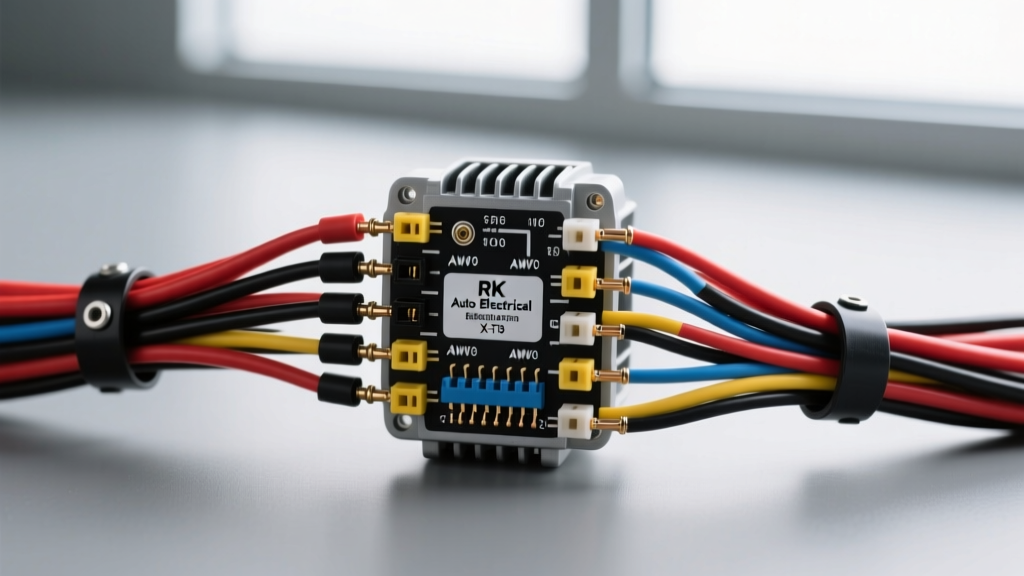
Introduction to RK Auto Electrical High-Output Systems
When upgrading a fleet vehicle, 4x4, or marine application with an RK Auto Electrical high-output alternator or heavy-duty gear-reduction starter, understanding the precise wiring architecture is critical. RK Auto Electrical components are engineered to meet rigorous OEM and severe-duty aftermarket standards, frequently utilizing Delco Remy and Denso core architectures modified for higher amperage output (ranging from 150A to 300A). Improper wiring of the voltage regulator pigtail or undersizing the B+ charge cable will result in immediate thermal failure, PCM communication faults, or chronic undercharging.
This technical specification reference provides the exact pinout configurations, wire gauge requirements, torque specifications, and diagnostic protocols necessary for correctly installing and troubleshooting RK Auto Electrical charging and cranking systems. All wiring practices referenced herein align with SAE J1128 Low Tension Primary Cable standards for under-hood automotive applications.
High-Output Alternator Regulator Pinouts
RK Auto Electrical alternators typically interface with the vehicle's Powertrain Control Module (PCM) or body control module (BCM) via specific multi-pin connectors. The two most common architectures supplied by RK are the Delco CS-series (Charging System) and the Denso SC-series (Segment Conductor).
Delco CS130D / CS144 2-Pin and 4-Pin Regulator Mapping
For RK alternators based on the Delco CS architecture, the internal voltage regulator relies on pulse-width modulation (PWM) signals from the PCM to determine the optimal charge rate. While the connector housing may have 4 cavities, many RK high-amp units only utilize 2 active pins.
| Pin | Designation | Function & Signal Type | Wire Color (Typical) |
|---|---|---|---|
| L | Lamp / Excitation | Receives 12V square wave PWM from PCM (128Hz). Dictates alternator turn-on and dash lamp status. | Gray or White/Black |
| F | Field / Feedback | Outputs PWM signal back to PCM indicating actual rotor field duty cycle (used for load management). | Red or Brown |
| S | Sense (4-Pin Only) | Direct battery voltage sense. Must be routed directly to the positive battery post or main distribution block. | Orange / Fusible Link |
| P | Phase (4-Pin Only) | Stator phase tap. Used for tachometer signal or legacy relay triggering. Rarely used on modern PCM-controlled RK units. | Yellow |
Technical Note: Never apply continuous 12V DC to the 'L' terminal on a PCM-controlled RK alternator. Doing so will bypass the PCM's load-management logic, forcing the alternator into maximum output continuously, which will boil the battery electrolyte and destroy the internal regulator diodes. For standalone (non-PCM) custom wiring harnesses, an external 12V PWM regulator or a specific resistor-diode dummy-load circuit must be utilized to excite the 'L' pin safely.
Denso SC1 / SC2 4-Pin Regulator Mapping
RK Auto Electrical's Denso-style high-output units (common in late-model Toyota, Lexus, and various Asian-market 4x4 applications) utilize a 4-pin connector that integrates LIN (Local Interconnect Network) bus communication or discrete ECU duty-cycle control.
| Pin | Designation | Function & Signal Type | Wire Color (Typical) |
|---|---|---|---|
| IG | Ignition | Switched 12V wake-up signal. Turns on the internal regulator logic circuit. | Black/White |
| L | Lamp | Dashboard charge indicator lamp ground path. | Yellow/Red |
| S | Sense | Battery voltage sense line. High impedance input. | White/Red |
| C | Computer / ECU | Receives variable duty-cycle signal from ECU to adjust target voltage (typically 13.5V to 14.8V). | Green/White |
According to Denso Automotive Alternator documentation, the 'C' terminal relies on a precise duty cycle. If the ECU wire is severed or shorted, the RK alternator will default to a fail-safe voltage of exactly 13.6V to protect the vehicle's electrical modules while still providing baseline charging.
Heavy-Duty Starter Solenoid Terminals & Routing
RK Auto Electrical gear-reduction starters feature heavy-duty copper-wound solenoids designed to handle the immense inrush current (often 800A to 1200A peak) required to crank large displacement diesel or high-compression gas engines. Correctly identifying the solenoid spade terminals is vital to prevent starter engagement runaway or ignition coil starvation during cranking.
- B Terminal (Battery): The primary high-current input. Accepts the main 1/0 AWG or 2/0 AWG cable directly from the battery positive post or front power distribution center. Torque spec for M10 stud: 15-20 Nm.
- M Terminal (Motor): Connects via a heavy copper braid or busbar directly to the starter motor housing. Never route external wiring to this terminal.
- S Terminal (Switch/Start): Receives the 12V crank signal from the ignition switch, starter relay, or PCM. Requires a minimum 12 AWG wire. Torque spec for M5/M6 nut: 3-5 Nm.
- I / R Terminal (Ignition/Run Bypass): Provides a 12V 'hot-in-crank' output to bypass the ballast resistor on legacy ignition systems, or to feed a secondary fuel pump relay during cranking. Only active while the starter is physically engaged.
AWG Sizing and Termination Standards for High-Amp Systems
Standard OEM wiring is entirely insufficient for RK Auto Electrical alternators rated above 140A. The factory B+ cable will suffer from severe voltage drop, generating excessive heat and potentially melting the factory insulation. You must upgrade the charge cable using SAE J1128 compliant cross-linked polyethylene (XLPE) wire, which is rated for continuous under-hood temperatures up to 125°C.
Current-to-Wire-Gauge Sizing Chart (Continuous Duty)
The following chart assumes a maximum cable run of 6 feet (alternator to battery) and a maximum allowable voltage drop of 0.5V.
| Alternator Max Output | Minimum AWG Size | Circular Mils | Recommended Lug Type |
|---|---|---|---|
| 100A - 120A | 4 AWG | 41,740 | Closed-Barrel Copper, Adhesive Heat Shrink |
| 130A - 160A | 2 AWG | 66,360 | Closed-Barrel Copper, Adhesive Heat Shrink |
| 170A - 220A | 1/0 AWG | 105,600 | Heavy-Duty Tinned Copper, Dual-Wall Polyolefin |
| 230A - 300A | 2/0 AWG | 133,100 | Heavy-Duty Tinned Copper, Dual-Wall Polyolefin |
Termination Best Practices
Never use solder on the B+ main charge cable lugs. Under high continuous amperage, the alternator B+ post can reach temperatures exceeding 150°C. Standard tin-lead solder begins to soften and lose mechanical integrity at 180°C, which can lead to catastrophic lug separation and an engine bay fire. Always use a calibrated hydraulic or ratcheting crimper for closed-barrel copper lugs, followed by 3M (or equivalent) adhesive-lined dual-wall heat shrink to prevent moisture ingress and galvanic corrosion at the copper-aluminum or copper-steel interface.
Diagnostic Voltage Drop Testing Protocol
If an RK Auto Electrical alternator is testing at 13.8V at the alternator B+ post but the battery is only seeing 13.1V, the system is suffering from parasitic voltage drop. Before replacing the alternator or PCM, perform the following Delco Remy approved diagnostic sequence:
- Preparation: Ensure the battery is fully charged and surface charge is removed. Turn on maximum electrical loads (HVAC blower on high, headlamps on high beam, rear defroster active) to force the RK alternator into maximum continuous output.
- Positive Side Drop Test: Set your Digital Multimeter (DMM) to DC Volts. Place the red probe directly on the alternator B+ output stud (not the nut, the stud itself). Place the black probe directly on the battery positive post. A reading greater than 0.5V indicates excessive resistance in the main charge cable, poor crimp terminations, or corroded intermediate fusible links.
- Negative Side Drop Test: Move the DMM red probe to the alternator case (bare metal, scrape away paint if necessary). Move the black probe to the battery negative post. A reading greater than 0.2V indicates a poor engine-to-chassis ground strap or a corroded battery negative terminal.
- Sense Wire Verification: Back-probe the 'S' (Sense) terminal on the alternator pigtail. Compare this voltage to the battery post voltage. If the sense wire reads more than 0.1V lower than the battery, the PCM is receiving false data and will overcompensate, leading to battery gassing and premature failure.
Summary of Installation Torque Specifications
Proper mechanical fastening is just as critical as electrical routing. Vibration in heavy-duty and off-road applications will loosen improperly torqued alternator terminals, leading to arcing and melted plastic insulator boots.
- Alternator B+ Stud (M8): 10 - 12 Nm (89 - 106 in-lbs)
- Alternator B+ Stud (M10): 15 - 20 Nm (11 - 15 ft-lbs)
- Alternator Mounting Bolts (M10 x 1.5): 45 - 55 Nm (33 - 40 ft-lbs)
- Starter Solenoid 'S' Terminal Nut (M5): 3 - 4 Nm (27 - 35 in-lbs)
- Starter B+ Terminal (M10): 15 - 20 Nm (11 - 15 ft-lbs)
By adhering to these RK Auto Electrical wiring specifications, pinout mappings, and SAE sizing standards, technicians and fabricators can ensure maximum efficiency, longevity, and safety of high-output automotive charging and cranking systems.