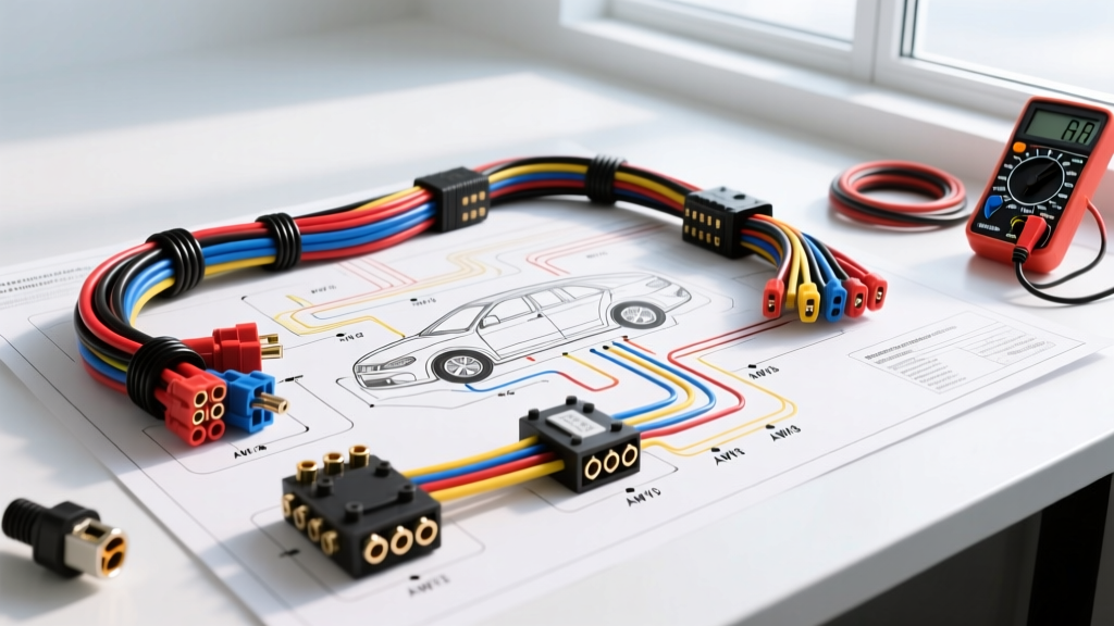
Mastering the Schematic: How to Read Auto Electrical Diagrams
Learning how to read auto electrical diagrams is the fundamental dividing line between a parts-swapper and a true diagnostic technician. Modern vehicle electrical architecture is a complex network of multiplexed data buses, pulse-width modulated (PWM) signals, and high-current power feeds. A wiring schematic is not just a map; it is a logical sequence of operations. When you understand how to trace power, verify grounds, and interpret component pinouts, you can isolate any electrical fault with surgical precision.
In this guide, we will break down the step-by-step troubleshooting flow using a real-world, high-failure circuit: the Fuel Pump Driver Module (FPDM) on the Ford F-150 5.4L V8. By applying this structured diagnostic flow, you will learn how to decode wire color codes, verify American Wire Gauge (AWG) specifications, and test specific connector pins using a high-impedance digital multimeter (DMM).
Step 1: Decode the Legend, Grid, and Wire Color Codes
Before touching a multimeter, you must understand the schematic's nomenclature. Automotive wiring diagrams rely on strict color-coding and grid-coordinate systems to route you through the harness.
Wire Color Nomenclature
Automotive wire colors are designated by a base color and a tracer (stripe) color. The base color is listed first, followed by the tracer. For example, a wire labeled RD/LG is Red with a Light Green tracer. A solid color is simply BK (Black) or RD (Red). According to the SAE J1128 Standard for low-tension primary cable, these color codes must remain consistent throughout the circuit to allow for rapid visual tracing.
Grid Coordinates and Splices
Manufacturer diagrams (such as those found in Haynes Wiring Diagram Manuals or OEM service portals) use an alphanumeric grid (e.g., Cell 4B) to indicate exactly where a wire routes off the page or connects to a splice pack. If you see a circle with an 'S' and a number (e.g., S104), this designates an inline copper crimp splice. If you see a 'G' (e.g., G101), this designates a chassis ground point. Knowing these coordinates prevents you from tearing apart the wrong section of the dashboard or engine bay harness.
Step 2: Identify Power Sources and Ground Topologies
Every circuit requires a complete path from the battery positive (B+) to the battery negative (Ground). The schematic will tell you exactly when the circuit is energized.
- B+ (Hot at All Times): Fed directly from the battery or main fuse block. Used for memory modules (PCM, BCM) and high-draw accessories.
- IGN (Ignition): Hot only when the key is in the RUN or START position. Fed through the ignition switch or BCM.
- ACC (Accessory): Hot when the key is in the ACCESSORY position (e.g., radio, power windows).
- GND (Ground): The return path to the battery. A schematic will show the ground routing to a specific bolt on the chassis or engine block.
Pro Tip: Never assume a ground is good just because the wire is bolted to the frame. Galvanic corrosion between a copper ring terminal and a steel chassis can introduce 2 to 5 ohms of resistance, which will completely disrupt a 5-volt reference sensor or a PWM control module.
Step 3: The Step-by-Step Troubleshooting Flow (FPDM Example)
Let us apply this knowledge to a diagnostic decision tree. The symptom is a no-start condition on a Ford F-150 5.4L. The fuel pump does not prime, and the OBD2 scanner shows a U0109 (Lost Communication With Fuel Pump Control Module) code. Here is how you read the diagram to test the FPDM circuit.
Diagnostic Decision Tree: FPDM Power and Ground
- Verify B+ Power Feed (Pin 4):
- Schematic Data: The diagram shows a 30-Amp fuse in the Smart Junction Box (SJB) feeding a 10 AWG Red (RD) wire to FPDM Connector C1, Pin 4.
- Action: Back-probe Pin 4 with your DMM. You should read battery voltage (12.2V - 12.6V).
- Failure Mode: If you read 0V, check SJB Fuse 27. If the fuse is blown, you likely have a short to ground in the 10 AWG Red wire where it rubs against the frame rail near the spare tire.
- Verify Chassis Ground (Pin 5):
- Schematic Data: The diagram routes a 12 AWG Black (BK) wire from FPDM Pin 5 to ground point G101 (left front frame rail).
- Action: Perform a voltage drop test across the ground circuit. Place the red lead on the battery negative post and the black lead on Pin 5. Crank the engine.
- Failure Mode: A reading over 0.1V indicates high resistance at G101. Remove the bolt, wire-brush the steel frame, apply dielectric grease, and torque to 9 Nm.
- Verify PCM PWM Signal (Pin 2):
- Schematic Data: A 18 AWG White/Violet (WT/VT) wire carries a Pulse-Width Modulated signal from PCM Connector C1, Pin 42 to FPDM Pin 2.
- Action: Connect an oscilloscope or a duty-cycle capable DMM to Pin 2. The PCM sends a variable duty cycle signal (typically 10% to 90%) to command fuel pressure.
- Failure Mode: If the signal is a flat 0V or a solid 12V, the PCM driver is faulty, or the 18 AWG WT/VT wire has a high-resistance fretting corrosion issue inside the Delphi Metri-Pack 150 connector cavity.
Step 4: Connector Pinouts and Real-World Failure Modes
Wiring diagrams do not just show wires; they show the physical connectors that join them. Understanding connector types is vital for physical troubleshooting. Most modern engine management sensors and control modules use sealed, weather-resistant connectors like the Delphi Metri-Pack or Weather-Pack series.
When the diagram points you to 'PCM C1 Pin 42', you must know how to physically locate that pin. Connectors are typically numbered based on a matrix grid visible on the connector face. Pin 1 is usually marked with a small triangle or a '1' molded into the plastic. In high-vibration environments, the female terminal inside the connector can experience 'fretting corrosion'—a micro-arcing phenomenon that builds up zinc oxide or copper oxide dust, increasing resistance without breaking the wire entirely. This is why voltage drop testing is vastly superior to simple continuity testing when diagnosing 18 AWG and 20 AWG signal wires.
Reference Chart: Automotive AWG and Circuit Application
When reading a diagram, the wire gauge is often noted next to the wire color (e.g., '1.0' for 1.0 square millimeters, or '18' for 18 AWG). Matching the correct replacement wire gauge is critical to prevent voltage drop and harness fires.
| AWG Size | Metric Equiv. | Max Ampacity (Automotive) | Typical Circuit Application | Common Color Code |
|---|---|---|---|---|
| 8 AWG | 8.0 mm² | 40A - 50A | Starter Solenoid, High-Amp Alternator B+ | RD (Red) |
| 10 AWG | 5.0 mm² | 30A | Fuel Pump Power, Cooling Fan Relays, FPDM Feed | RD (Red) or YE (Yellow) |
| 12 AWG | 3.0 mm² | 20A | Headlight Power Feeds, Main Chassis Grounds | BK (Black) or BU (Blue) |
| 16 AWG | 1.5 mm² | 10A | Interior Lighting, Horn Relay Control, Power Windows | VT (Violet) or OG (Orange) |
| 18 AWG | 0.8 mm² | 5A - 7A | Sensor 5V Reference, PCM PWM Signals, Injector Drivers | WT/VT (White/Violet) or GY (Gray) |
| 20 AWG | 0.5 mm² | 3A | CAN High / CAN Low Data Bus, Airbag Clockspring | DG/LG (Dark Green/Light Green) |
Advanced Diagnostic Takeaways
Knowing how to read auto electrical diagrams transforms a chaotic wiring harness into a logical, testable sequence. Always start at the power source, verify the integrity of the ground using a voltage drop test, and finally test the control signal or data bus. By cross-referencing the schematic's wire colors, AWG ratings, and connector pinouts with physical measurements at the component, you eliminate guesswork and ensure permanent, reliable electrical repairs.