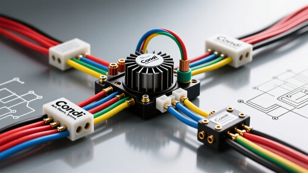
Advanced Architecture of Condi Auto Electric Systems
The term "condi auto electric" encompasses the complex, integrated electrical network responsible for managing a vehicle's air conditioning and climate control systems. Unlike basic lighting or accessory circuits, modern automotive HVAC electrical architecture requires precise coordination between the Powertrain Control Module (PCM), high-amperage condenser cooling fans, variable displacement compressor controls, and solid-state refrigerant pressure transducers. A failure in any single node of this network can result in catastrophic compressor damage, PCM driver burnout, or complete loss of cabin cooling.
This advanced technical deep dive explores the wiring schematics, pinout configurations, wire gauge specifications, and real-world failure modes of condi auto electric circuits. Whether you are diagnosing a parasitic draw from a sticking condenser fan relay or mapping the Pulse Width Modulation (PWM) signal of a modern variable swashplate compressor, understanding the foundational electrical parameters is critical for accurate diagnostics.
AC Compressor Clutch Circuits: Fixed Displacement Systems
Traditional fixed-displacement compressors utilize an electromagnetic clutch coil to engage the drive pulley to the compressor shaft. The electrical demands of this coil are deceptively high. A standard clutch coil operates at 12V DC and typically exhibits a resistance between 3.5 and 4.5 ohms when measured at 68°F (20°C). According to Ohm's Law, this translates to an operating current draw of roughly 2.6 to 3.4 amps.
Wiring Specifications and Connector Types
The primary power feed to the compressor clutch relay and the subsequent feed to the clutch coil must be sized to handle the inrush current without excessive voltage drop. Automotive manufacturers typically utilize 14 AWG copper wire for the clutch power feed, often color-coded as Dark Green with a White tracer (GM) or Light Green/Black (Ford). The ground circuit, which usually routes through the engine block or a dedicated chassis ground point, utilizes 16 AWG Black or Black/White wire.
At the compressor pigtail, the connection is almost universally a Metri-Pack 150.2 2-pin weather-sealed connector. A common failure mode in older vehicles is the degradation of the silicone weather seal, allowing moisture ingress that leads to terminal oxidation. When terminal resistance exceeds 0.5 ohms, the voltage reaching the coil drops below the 10.5V threshold required to maintain the magnetic field, resulting in clutch slip, rapid cycling, and eventual coil burnout.
The Critical Role of the Flyback Diode
When the PCM de-energizes the clutch relay, the collapsing magnetic field of the clutch coil generates a massive reverse voltage spike (back-EMF), often exceeding 100 volts. To protect the PCM's internal low-side driver transistor, a flyback diode or suppression resistor is wired in parallel across the clutch coil or integrated into the relay harness. If a technician replaces a factory clutch pigtail and omits this suppression circuit, the back-EMF will instantly destroy the PCM's internal driver, leading to a permanent short-to-ground condition within the module.
Variable Displacement Compressors: PWM Control Logic
Modern vehicles have largely abandoned the traditional magnetic clutch in favor of variable displacement compressors (VDC). These compressors remain mechanically engaged at all times but alter their internal stroke via an electronically controlled swashplate. The condi auto electric circuit for a VDC is radically different from a fixed clutch.
Instead of a simple 12V on/off relay, the PCM controls the compressor via a Pulse Width Modulation (PWM) signal. The electrical connector is typically a 2-pin Metri-Pack 150. Pin A receives a constant 12V ignition-switched feed (usually 14 AWG Red or Pink wire), while Pin B is the PWM control circuit routed directly to the PCM (18 AWG Brown/White or Gray wire). The PCM modulates the ground path at a frequency of roughly 100 Hz to 500 Hz, varying the duty cycle from 10% (minimum stroke) to 90% (maximum stroke) based on cabin thermal load and evaporator temperature sensors.
Diagnostic Tip: A standard digital multimeter (DMM) will only show an average voltage (e.g., 7V) on the PWM line. To properly diagnose a VDC control circuit, an automotive oscilloscope is mandatory to verify the square wave pattern and ensure the duty cycle commands from the PCM match the physical pressure output of the compressor.
Condenser Fan Relay Logic and High-Amperage Routing
The condenser fan is the unsung hero of the condi auto electric system. Without adequate airflow across the condenser fins, the high-side pressure will skyrocket, triggering the pressure transducer to command the compressor offline. Modern condenser fans draw between 30 and 50 amps under high-load conditions, necessitating robust wiring and heavy-duty switching mechanisms.
Wiring and Fuse Sizing
Power is routed from the Battery Electric Center (BEC) or Underhood Fuse Block via a 40A or 50A Maxi-fuse. The primary feed wire is heavily insulated 10 AWG (often Red or Orange) to minimize voltage drop over the distance from the battery to the front fascia. Because of the high amperage, manufacturers utilize either heavy-duty ISO micro-relays rated for 70A, or solid-state Fan Control Modules (FCMs) that use PWM to vary fan speed based on high-side refrigerant pressure and engine coolant temperature.
When diagnosing a dead condenser fan, always perform a voltage drop test across the Maxi-fuse and the relay load contacts. A voltage drop greater than 0.2V across the fuse indicates internal corrosion or a fatigued fuse element that is restricting current flow, even if the fuse appears visually intact.
Refrigerant Pressure Transducer Signal Mapping
The PCM relies on the refrigerant pressure transducer to dictate compressor engagement, fan speed, and over-pressure protection. Unlike older binary or trinary pressure switches that simply open or close contacts, the modern transducer is a linear 3-wire sensor.
| Pin Number | Function | Typical Wire Color | Wire Gauge | Voltage Specification |
|---|---|---|---|---|
| Pin 1 | 5V Reference | Red or Gray | 20 AWG | 4.8V - 5.2V (Key On, Engine Off) |
| Pin 2 | Signal Return | Light Green or Yellow | 20 AWG | 0.5V (0 psi) to 4.8V (450+ psi) |
| Pin 3 | Sensor Ground | Black or Black/White | 20 AWG | Less than 0.05V drop to battery negative |
If the 5V reference circuit (Pin 1) shorts to ground due to chafing against the condenser bracket, the PCM will register a 0V signal, interpreting it as a catastrophic loss of refrigerant, and will permanently lock out the compressor clutch or VDC control valve. Always verify the 5V reference with a high-impedance DMM before condemning the sensor.
Diagnostic Decision Tree: Compressor Fails to Engage
When approaching a condi auto electric failure, systematic elimination of the control and load circuits is required. Follow this decision tree to isolate the fault:
- Step 1: Verify Refrigerant Charge. Connect manifold gauges. If static pressure is below 40 psi, the low-pressure threshold of the transducer will inhibit the PCM from grounding the clutch relay. Fix mechanical leaks before electrical diagnostics.
- Step 2: Command Relay via Scan Tool. Use a bi-directional scanner to command the AC compressor relay ON.
- If relay clicks but clutch does not engage: Fault is in the load circuit (14 AWG power feed, clutch coil, or ground).
- If relay does not click: Fault is in the control circuit (PCM driver, relay coil ground, or ignition feed to relay).
- Step 3: Load Circuit Voltage Drop. With the relay commanded ON, back-probe the clutch connector. Measure voltage between the power pin and battery negative (should be >11.5V). Measure voltage between the ground pin and battery positive (should be <0.5V).
- Step 4: Coil Resistance Check. Disconnect the pigtail and measure resistance across the clutch coil pins. If reading is OL (open) or below 2.0 ohms (shorted), replace the clutch coil assembly.
Real-World Failure Modes and Parasitic Draws
One of the most insidious condi auto electric issues is a parasitic battery draw caused by a sticking condenser fan relay or a shorted clutch diode. Because these circuits are often fed directly from the battery (B+) via the underhood fuse block to allow for "after-blow" or post-shutdown cooling, a welded relay contact will drain a 70Ah battery overnight.
To diagnose, perform a global parasitic draw test. If the draw exceeds 50mA after module sleep (typically 20-45 minutes), pull the AC Maxi-fuse and the Condenser Fan fuse in the BEC. If the draw drops to normal, isolate the circuit by unplugging the Fan Control Module and the compressor clutch pigtail. According to diagnostic methodologies outlined by MACS Worldwide, thermal cycling of underhood relays frequently causes the internal copper contacts to micro-weld, a failure mode that requires replacing the entire relay block or BEC assembly, as individual relays are often soldered to the board in modern architectures.
Furthermore, adherence to SAE J1739 FMEA guidelines suggests that harness routing near the condenser is highly susceptible to road debris impact. Always inspect the lower radiator air deflector and ensure the 10 AWG condenser fan harness is securely zip-tied and shielded from the cooling fan blades and gravel deflection.
Conclusion
Mastering condi auto electric systems requires moving beyond simple 12V test lights and embracing oscilloscopes, voltage drop testing, and an intimate understanding of PCM logic strategies. By respecting the AWG requirements, verifying Metri-Pack terminal tension, and understanding the vital role of flyback suppression and PWM duty cycles, automotive electrical technicians can accurately diagnose and permanently repair complex HVAC electrical faults.