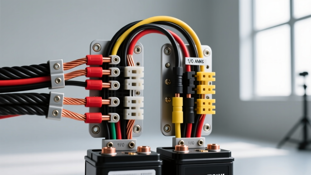
The Max's Auto Electric Philosophy: High-Amperage Architecture
In the realm of heavy-duty off-road, expedition, and racing vehicle builds, the 'Max's Auto Electric' methodology has become a benchmark for high-amperage charging system architecture. When upgrading from a standard 80A OEM alternator to a 200A+ high-output unit (such as the Denso SC14 or Leece-Neville 2800 series), standard automotive wiring practices fail catastrophically. The Max's Auto Electric blueprint prioritizes minimal voltage drop, thermal stability, and precise regulator sensing to protect sensitive AGM and Lithium-Iron-Phosphate (LiFePO4) secondary batteries.
This advanced technical deep dive dissects the exact wiring specifications, connector protocols, and diagnostic matrices that define the Max's Auto Electric standard for dual-battery management and high-output alternator integration.
Core Principles of the 200A+ Charging System
Standard OEM wiring relies on the vehicle's chassis as a primary ground return and utilizes thin 14 AWG sense wires routed through degraded factory harnesses. Under a 200A continuous load, this architecture induces severe voltage drop. According to SAE J1128 standards for low-tension primary cables, resistance increases exponentially with temperature. The Max's methodology dictates dedicated, oversized ground straps and direct-to-terminal remote sensing to ensure the alternator's internal voltage regulator reads the true state of charge at the battery posts, not at the alternator B+ terminal.
Component Selection and AWG Specifications
The foundation of the Max's Auto Electric blueprint is the strict adherence to cross-linked polyethylene (XLPE) insulated cabling and mil-spec adhesive-lined heat shrink. PVC insulation becomes brittle and melts near high-heat exhaust manifolds, whereas XLPE maintains dielectric integrity up to 150°C.
| Circuit Application | AWG Size / Metric | Strand Count | Crimp Die Size (Hex) | Heat Shrink Ratio |
|---|---|---|---|---|
| Alternator B+ to Primary Battery | 1/0 AWG (53.5mm²) | 4130 / 36 AWG | 50mm² Hex Die | 3:1 Adhesive-Lined |
| Primary to Secondary Battery Link | 2 AWG (33.6mm²) | 2590 / 36 AWG | 35mm² Hex Die | 3:1 Adhesive-Lined |
| Alternator Case to Chassis Ground | 2 AWG Braided Copper | Flat Braid | 35mm² Hex Die | 3:1 Adhesive-Lined |
| Regulator Sense Wire (S-Terminal) | 10 AWG (5.26mm²) | 1050 / 30 AWG | 6mm² Hex Die | 2:1 Standard Polyolefin |
| Ignition Exciter (IG-Terminal) | 14 AWG (2.08mm²) | 411 / 34 AWG | 2.5mm² Hex Die | 2:1 Standard Polyolefin |
Step-by-Step: The Dual-Battery Isolator Wiring Sequence
Executing the Max's Auto Electric dual-battery sequence requires precision. The most common failure mode in high-amp builds is a voltage drop across the isolator solenoid or poor crimp oxidation. Follow this exact sequence for a Denso SC14 220A alternator upgrade paired with a smart VSR (Voltage Sensitive Relay) isolator.
Step 1: Alternator B+ and Main Charge Cable Routing
Do not route the main charge cable to the starter solenoid. The Max's standard requires a dedicated 1/0 AWG XLPE cable routed directly from the alternator B+ terminal to the primary battery positive post. Install a 250A Class T fuse within 7 inches of the battery positive terminal. Torque the M8 alternator B+ nut to exactly 12-15 Nm. Over-torquing will strip the soft copper internal stator lead; under-torquing will cause micro-arcing and thermal runaway.
Step 2: The Dedicated Ground Strap
Alternator cases painted or powder-coated by aftermarket manufacturers act as insulators. Scrape away all paint on the alternator mounting ear and the engine block mating surface down to bare metal. Apply a thin layer of conductive copper anti-seize. Install a 2 AWG braided copper ground strap directly from the alternator case to the primary battery negative terminal. Torque the M10 battery terminal nut to 20-25 Nm.
Step 3: Denso SC14 Regulator Pinout and Sense Wiring
The Denso 3-pin connector is the heart of the charging logic. Miswiring this plug will result in immediate overcharging and AGM battery off-gassing.
- Pin 1 (IG - Ignition): Connect a 14 AWG Red/White wire to a clean, ignition-switched 12V source. This wakes the regulator. Protect with a 5A mini-fuse.
- Pin 2 (L - Lamp): Connect an 18 AWG Green wire to the dash charge indicator lamp. If using an LED dash indicator, install a 470-ohm resistor in parallel to prevent the regulator from reading an open circuit and failing to excite the rotor field.
- Pin 3 (S - Sense): This is the most critical wire. Run a dedicated 10 AWG White wire directly from the S-terminal to the secondary battery positive post. Protect with a 15A maxi-fuse at the battery end. By sensing at the secondary battery, the alternator will push maximum voltage (up to 14.6V) to overcome the voltage drop of the long cable runs and the VSR solenoid, ensuring the auxiliary battery reaches 100% State of Charge (SoC).
Advanced Troubleshooting: Voltage Drop & Parasitic Draw
When a high-amp system fails to charge correctly, amateur mechanics often replace the alternator. The Max's Auto Electric diagnostic matrix relies on loaded voltage drop testing. As outlined in SAE J56 Alternator Test Procedures, an alternator must be evaluated under loaded conditions, not just at idle with no accessories.
| Symptom | Probable Cause | Max's Diagnostic Fix & Specification |
|---|---|---|
| Secondary battery stuck at 12.4V under heavy load (winching/fridge). | Excessive voltage drop across the VSR solenoid or undersized inter-battery cable. | Measure voltage drop across VSR with 100A load. If >0.15V, replace solenoid with a solid-state MOSFET isolator or upgrade inter-battery cable to 1/0 AWG. |
| Alternator B+ terminal melting or showing heat discoloration. | Micro-arcing due to improper crimp or incorrect torque on the B+ nut. | Cut off terminal. Strip 1/0 AWG wire exactly 22mm. Use hydraulic hex-crimp. Torque M8 nut to 14 Nm. Apply dielectric grease over the nut. |
| AGM secondary battery bulging or venting gas. | Sense wire (S-terminal) broken or high resistance, causing regulator to max out field current. | Test S-wire continuity. Voltage at S-pin must be within 0.05V of battery post voltage. Repair wire and check 15A inline fuse. |
| Parasitic draw of 400mA+ when vehicle is off. | VSR solenoid coil remaining energized due to back-feeding from the IG circuit. | Install a blocking diode (e.g., 50A stud-mount) on the VSR trigger wire to prevent secondary battery back-feed into the ignition circuit. |
Thermal Management and Connector Chemistry
A frequently overlooked aspect of the Max's Auto Electric standard is connector chemistry. When joining copper lugs to aluminum terminals (such as the B+ post on many modern high-amp alternators), galvanic corrosion occurs rapidly in the presence of moisture and road salt. This corrosion creates a high-resistance semiconductor layer that generates immense heat under 150A+ loads.
To prevent this, the Max's methodology mandates the use of NO-OX-ID 'A-Special' or a similar zinc-based antioxidant paste applied directly to the mating surfaces of the lug and terminal before torquing. Furthermore, all crimped lugs must utilize 3:1 adhesive-lined heat shrink. The inner layer of hot-melt adhesive flows into the wire strands during the shrinking process, creating a hermetic seal that prevents capillary action from drawing moisture under the insulation jacket.
Conclusion and Industry Alignment
Building a high-output dual-battery system is not simply a matter of bolting on a larger alternator; it requires a fundamental rethinking of the vehicle's electrical architecture. By adhering to the Max's Auto Electric blueprint—prioritizing oversized XLPE cabling, dedicated remote sensing, precise torque specifications, and galvanic corrosion prevention—you ensure that your expedition or racing vehicle maintains absolute electrical integrity under the most extreme loads. For further reading on heavy-duty electrical standards and alternator testing protocols, consult the Bosch Mobility Solutions Charging Systems documentation and relevant SAE technical papers.