The Professional Standard: Engineering a Bulletproof Charging System
When benchmarking professional-grade harness fabrication and high-output charging system installations, the methodologies championed by elite institutions like Manny's Auto Electric serve as the industry baseline. Upgrading to a high-amp alternator is not simply a matter of bolting on a larger unit and hoping the factory wiring can handle the current. In heavily modified vehicles, classic restomods, or off-road rigs running auxiliary lighting and winches, the factory charge wire and internal voltage regulators will quickly become a bottleneck, leading to voltage drop, melted insulation, and catastrophic electrical failure.
This practical installation guide breaks down the professional approach to high-amperage alternator wiring. We will cover load auditing, proper AWG sizing for high-heat engine bay environments, precise 3-wire alternator pinouts, and the critical termination techniques that separate professional auto electricians from amateur DIYers.
Phase 1: The Electrical Load Audit
Before selecting an alternator or routing a single wire, you must calculate the maximum continuous electrical load of the vehicle. The 'Manny's Auto Electric' philosophy dictates that your alternator's rated output should exceed your maximum continuous load by at least 20% to account for heat derating and idle-speed inefficiencies.
Common High-Draw Accessory Loads
| Component | Typical Amperage Draw | Notes / Duty Cycle |
|---|---|---|
| Electric Cooling Fans (Dual) | 35A - 50A | Continuous at operating temp |
| Electronic Fuel Injection (V8) | 25A - 40A | Includes injectors and high-pressure pump |
| Electric Water Pump | 8A - 15A | Continuous |
| Off-Road LED Light Bars | 15A - 30A | Intermittent / Night use |
| High-Power Audio Amplifiers | 50A - 120A+ | Peaks during heavy bass transients |
| Ignition System (CDI / MSD) | 8A - 12A | Continuous at high RPM |
Once you sum your continuous and intermittent loads, select an alternator that meets the requirement at engine idle speed, not just at 5,000 RPM. For most heavily modified V8 applications, a 140-Amp to 180-Amp alternator (such as the GM CS144 or Denso SC14 platform) is the minimum requirement.
Phase 2: High-Amp Alternator Selection and Pulley Ratios
A common failure point in high-output installations is incorrect pulley sizing. An alternator must reach its 'cut-in' speed to begin charging. According to Powermaster's technical documentation, most high-amp alternators require a minimum rotor speed of 2,400 RPM to produce rated output. If your engine idles at 800 RPM, your crank pulley must be at least 2.5 to 3 times larger in diameter than the alternator pulley. Always verify the pulley ratio before finalizing your belt routing.
Phase 3: The 3-Wire Alternator Pinout and Routing
While '1-wire' self-exciting alternators are popular for their simplicity, they are fundamentally flawed for high-draw vehicles. They require high RPMs to 'turn on' and often suffer from poor voltage regulation because they sense voltage at the alternator case, not the battery. Professional shops exclusively use 3-wire setups for precision voltage regulation.
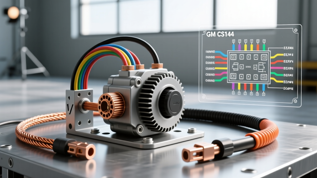
GM CS130D / CS144 3-Wire Pin Configuration
| Terminal Pin | Function | Wire Gauge (AWG) | Routing Destination |
|---|---|---|---|
| L (Lamp/Exciter) | Turns on the internal regulator. Can also drive a dash warning light. | 10 AWG TXL | Ignition-switched 12V source (use a 560-ohm resistor in parallel if no dash bulb is used). |
| S (Sense) | Reads actual battery voltage to adjust charging output. | 10 AWG TXL | Direct to Battery Positive (+) terminal. Must include an inline 10A fuse. |
| Main Output (BAT) | Primary charge wire carrying the bulk of the amperage. | 1/0 AWG Welding Cable | Direct to Battery Positive (+) or main starter solenoid post (if starter is directly tied to battery). |
Note: TXL (Cross-linked) wire is mandatory for engine bay routing. Standard PVC wire will melt and become brittle. TXL wire is rated for continuous 125°C operation and meets SAE J1128 specifications for low-voltage primary cable.
Phase 4: Termination and the 'No-Solder' Rule
One of the most closely guarded secrets of high-end auto electric shops is the absolute rejection of solder in the engine bay. While solder is excellent for interior PCB work or low-vibration dash wiring, it is a liability in high-heat, high-vibration environments. Solder wicks up into the wire strands under capillary action, creating a hard, inflexible point. Engine vibration causes the wire to fatigue and snap exactly at the edge of the solder joint.
The Professional Crimping Methodology
- Strip the Wire: Use a precision wire stripper to avoid nicking the copper strands. Nicked strands reduce the cross-sectional area and create hot spots.
- Select the Terminal: Use heavy-duty, closed-end copper ring terminals (not stamped brass or aluminum). The terminal barrel must match the AWG of the wire exactly.
- Hex-Crimp: Use a ratcheting hex-crimp tool or a hydraulic crimper. A hex crimp deforms the copper terminal into the wire strands, creating a cold-weld that is both mechanically and electrically superior to solder.
- Adhesive Heat Shrink: Seal the termination with dual-wall, adhesive-lined marine heat shrink. When heated, the inner lining melts and flows into the wire strands, creating a waterproof, corrosion-proof seal that prevents green rot (copper oxidation).
Phase 5: Circuit Protection and Fusing
The main 1/0 AWG charge wire must be protected. If the alternator's internal diode trio shorts to ground, the alternator will attempt to dump the battery's entire cold-cranking amp (CCA) capacity through the charge wire, resulting in an engine bay fire. Install a 150A to 200A Mega Fuse (or ANL fuse) on the main charge wire. Crucially, this fuse must be located within 7 inches of the battery positive terminal, not near the alternator. The wire between the battery and the fuse is entirely unprotected; keeping it as short as possible eliminates the risk of a dead short.
Phase 6: Validation via Voltage Drop Testing
Never rely on a simple multimeter reading at the battery to validate a charging system. You must perform a voltage drop test under load to identify hidden resistance in the cables, crimps, and grounds. According to Painless Performance wiring guides, a healthy circuit should exhibit minimal voltage loss.
SAE Acceptable Voltage Drop Limits
| Circuit Segment | Maximum Acceptable Drop | Testing Procedure |
|---|---|---|
| Alternator BAT Post to Battery (+) | < 0.20 Volts | Multimeter leads on Alt BAT post and Battery (+) while engine is at 2000 RPM with fans on. |
| Alternator Case to Battery (-) | < 0.10 Volts | Multimeter leads on Alt Case (clean metal) and Battery (-) terminal. |
| Engine Block to Chassis Ground | < 0.10 Volts | Essential for EFI and sensor reference grounds. Test under cranking load. |
Summary of the Professional Approach
Adopting the rigorous standards seen at Manny's Auto Electric transforms a vehicle's electrical system from a recurring headache into a set-and-forget asset. By utilizing TXL wire, adhering to strict 3-wire alternator pinouts, executing hex-crimp terminations with adhesive heat shrink, and validating the system via voltage drop testing, you ensure that your high-amp charging system will deliver clean, stable voltage to every ECU, injector, and ignition coil on the vehicle, regardless of the operating environment.