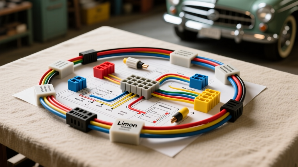
Introduction to the Limon Auto Electric Harness System
When performing a complete restomod or custom classic car build, upgrading the electrical architecture is non-negotiable. The Limon Auto Electric universal wiring harness system has become a staple in the hot rod and classic muscle car community due to its robust 21-circuit fuse block, sealed bulkhead connectors, and high-temperature GXL (Cross-Linked Polyethylene) wire insulation. According to the SAE J1128 Low Tension Primary Cable Standard, GXL wire offers superior thermal resistance and a thinner wall profile compared to standard PVC, allowing for tighter routing in cramped engine bays without sacrificing amperage capacity.
However, even the most premium harness requires meticulous installation. A misrouted ignition feed or an undersized ground path can lead to catastrophic voltage drops or electrical fires. This complete wiring diagram walkthrough will dissect the core circuits of the Limon Auto Electric system, providing actionable pinouts, wire gauge specifications, and real-world troubleshooting strategies for your build.
Main Fuse Block Layout and Circuit Protection
The heart of the Limon system is the 21-circuit ATO/ATC fuse block, typically mounted on the firewall or under the dash. The main power feed enters the block via a 10 AWG Red wire protected by a 60A Mega Fuse located within 18 inches of the battery positive terminal. This adheres to best practices outlined in Automotive Electricity and Electronics by James D. Halderman, which mandates overcurrent protection as close to the power source as possible.
Primary Circuit Assignments
| Circuit # | Function | Wire Color | AWG Size | Fuse Rating |
|---|---|---|---|---|
| 1 | Headlight Feed (Relay Coil) | White | 14 | 10A |
| 2 | Parking / Tail Lights | Brown | 14 | 15A |
| 3 | Left Front Turn / Marker | Yellow | 14 | 10A |
| 4 | Right Front Turn / Marker | Dark Green | 14 | 10A |
| 5 | Ignition Switched (HEI / EFI) | Pink | 12 | 20A |
| 6 | Starter Solenoid 'S' Terminal | Purple | 10 | 30A |
| 7 | Electric Fuel Pump | Orange | 12 | 15A |
| 8 | Wiper Motor Feed | Gray | 12 | 15A |
| 9 | Horn Relay Coil | Dark Blue | 14 | 10A |
| 10 | Radio / Accessory Memory | Yellow (Fused) | 14 | 10A |
Note: Always use a ratcheting crimper specifically calibrated for ATO fuse terminals and Weather-Pack seals to ensure gas-tight connections, preventing micro-arcing inside the fuse block.
Bulkhead Connector Pinout Walkthrough
The engine-to-cabin bulkhead connector is the most common failure point in custom builds. The Limon harness utilizes a 24-pin sealed Weather-Pack style rectangular connector. Proper pin insertion requires stripping exactly 3/16 inch of insulation and crimping the terminal before sliding the silicone weather seal over the wire jacket. Below is the critical pin mapping for the primary drivetrain and lighting circuits crossing the firewall.
Firewall Bulkhead Pin Configuration (Cabin to Engine Bay)
| Pin | Circuit Description | Wire Color | AWG | Destination |
|---|---|---|---|---|
| 1 | Main Ignition 12V Switched | Pink | 12 | HEI Distributor / ECU Main Relay |
| 2 | Starter Engage Signal | Purple | 10 | Starter Solenoid 'S' Post |
| 3 | Alternator Exciter (Alt #1) | Brown | 16 | Alternator 'L' or '1' Terminal |
| 4 | Alternator Sense (Alt #2) | Red | 14 | Alternator 'S' or '2' Terminal |
| 5 | Left Low Beam Headlight | Yellow | 14 | Left Headlight Bucket |
| 6 | Right Low Beam Headlight | Dark Green | 14 | Right Headlight Bucket |
| 7 | High Beam Feed (Shared) | Light Green | 12 | Dimmer Switch High Beam Out |
| 8 | Engine Bay Accessory (BATT) | Red | 10 | Relay Bank Constant 12V Feed |
Ignition and Starter Circuit Routing
The ignition and starter circuits demand the highest transient current handling in the vehicle. In the Limon diagram, the starter circuit originates at the ignition switch 'START' terminal. A 10 AWG Purple wire routes through the neutral safety switch (if equipped with an automatic transmission) and enters the bulkhead at Pin 2. This wire terminates at the 'S' terminal on the starter solenoid.
Critical Installation Note: Never route the 10 AWG Purple starter wire parallel to the ignition coil primary wires or EFI injector harnesses. The massive inductive spike generated when the starter solenoid disengages can induce electromagnetic interference (EMI), causing ECU resets or misfires. Maintain at least a 4-inch separation from sensitive logic circuits, a principle heavily emphasized in Bosch Automotive Electrics and Electronics.
For the ignition feed, the 12 AWG Pink wire (Pin 1) supplies switched 12V to the HEI distributor or EFI main relay. Ensure this circuit is completely isolated from the 'Accessory' position of the ignition switch; the engine management system must only receive power in the 'RUN' and 'START' positions to prevent back-feeding through the coil during cranking.
Lighting Architecture and Relay Integration
Classic vehicles originally relied on the headlight switch to carry the full amperage load of the headlights, resulting in severe voltage drops and dim illumination. The Limon Auto Electric diagram solves this by utilizing a dedicated 30A headlight relay mounted in the engine bay.
- Trigger Circuit: A 14 AWG White wire carries a low-amperage trigger signal from the cabin headlight switch to the relay coil (Pin 85).
- Power Feed: A 10 AWG Red wire feeds the relay contact (Pin 30) directly from the engine bay fuse distribution block.
- Output: The relay output (Pin 87) sends 12 AWG power to the dimmer switch, which then splits into 14 AWG Yellow (Left Low), 14 AWG Dark Green (Right Low), and 12 AWG Light Green (High Beams).
This architecture ensures that the headlights receive full battery voltage minus only a fraction of a volt, maximizing lumen output and ensuring the floor-mounted dimmer switch does not overheat.
Grounding Strategy and Specifications
An automotive electrical system is only as reliable as its ground paths. The Limon diagram dictates a star-grounding topology rather than relying on daisy-chained body panels. You must install the following dedicated ground cables using 3/8 inch ring terminals, star washers, and bare metal contact points treated with dielectric grease after torquing:
- Main Battery Ground: 4 AWG cable from battery negative to the engine block (torque to 35 ft-lbs on the cylinder head bolt).
- Engine to Chassis Ground: 8 AWG braided strap from the rear of the intake manifold to the firewall. This provides the return path for the alternator and starter.
- Dash Harness Ground: 12 AWG Black wire from the main fuse block ground bus to a dedicated threaded boss on the steering column support bracket.
- Rear Lighting Ground: 14 AWG Black wire terminating in a ring terminal bolted directly to the rear crossmember, independent of the taillight housing threads.
Troubleshooting Common Limon Harness Issues
Even with a flawless diagram, installation errors occur. Use this diagnostic decision tree to isolate the most frequent faults encountered during initial power-up.
Symptom: Dash Illumination Flickers When Turn Signals Engage
- Root Cause: Shared ground path between the instrument cluster and the turn signal flasher, or an undersized tail light feed causing a voltage drop that back-feeds through the dash bulbs.
- Diagnostic Step: Perform a voltage drop test across the dash harness ground wire. Place the multimeter leads on the battery negative post and the dash ground ring terminal. Actuate the turn signal.
- Acceptable Limit: A reading above 0.2V indicates excessive resistance. Clean the firewall grounding point and upgrade the dash ground to 10 AWG.
Symptom: Starter Solenoid Chatters or Fails to Engage on Hot Starts
- Root Cause: Voltage drop across the bulkhead connector Pin 2 (Purple wire) or the neutral safety switch. Heat soak from the exhaust headers increases the resistance of the copper wire and brass bulkhead terminals.
- Diagnostic Step: Measure voltage at the ignition switch 'START' terminal during cranking, then measure at the starter 'S' terminal. Compare the two.
- Acceptable Limit: If the drop exceeds 1.0V, inspect the bulkhead connector for improperly crimped Weather-Pack pins. Extract the pin using a Delphi extraction tool, re-crimp with a fresh terminal, and ensure the secondary lock (TPA) is fully seated.
Symptom: Alternator Fails to Charge at Idle
- Root Cause: The 16 AWG Brown exciter wire (Bulkhead Pin 3) is missing the required inline 10-ohm, 2-watt resistor or diode, causing the alternator field to fail to energize at low RPMs.
- Fix: Splice a 10-ohm ceramic resistor into the Brown wire within 6 inches of the alternator 'L' terminal, or install a dedicated 1-Amp diode pointing toward the alternator to prevent back-feeding into the dash warning light circuit.
By strictly adhering to the Limon Auto Electric wiring diagram, utilizing proper GXL wire, and executing precision crimps on all Weather-Pack and Metri-Pack terminals, you will build an electrical architecture capable of supporting modern EFI systems, high-draw cooling fans, and premium audio without compromising safety or reliability.