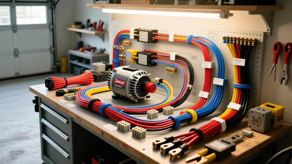
Designing the Main Power Architecture for High-Amp Testing
When executing complex vehicle electrical modifications, validating high-draw components before installation saves hours of under-hood troubleshooting. Establishing a dedicated garage auto electric test bench allows you to bench-test high-output alternators (200A–300A) and 12V electric AC compressors under continuous load. The foundation of this setup is a robust, low-resistance power architecture capable of handling extreme current without thermal runaway or excessive voltage drop.
For a bench designed to test 250A+ alternators, standard primary wire is insufficient. You must utilize 1/0 AWG fine-strand copper welding cable that complies with the SAE J1128 standard for low-tension primary cable. This specific insulation resists the high heat generated near the alternator B+ terminal and offers superior flexibility for bench routing.
Voltage Drop and Feed Sizing
A 250A load across a 6-foot run of 1/0 AWG copper wire yields a voltage drop of approximately 0.30V. While acceptable, upgrading the main positive and negative busbars to 3/8-inch copper stock ensures minimal resistance. Always route the main ground directly from the alternator casing mounting ear to the negative busbar using a dedicated 1/0 AWG cable, rather than relying on the bench frame, which can introduce stray resistance and skew regulator sense readings.
Wiring the Denso High-Output Alternator Harness
The Denso internally regulated alternator is the gold standard for automotive upgrades due to its high efficiency and compact footprint. However, bench-testing a Denso unit requires precise excitation of the internal voltage regulator via its 3-pin connector. Improperly wiring this plug on the bench will result in the alternator failing to charge or defaulting to a base voltage of 13.2V.
| Pin | Label | Function | Bench Wire AWG | Bench Connection Protocol |
|---|---|---|---|---|
| 1 | L (Lamp) | Excites the internal regulator and drives the dash charge lamp. | 18 AWG | Connect to +12V via a 1kΩ resistor or a standard 194 incandescent bulb to simulate dash load. |
| 2 | IG (Ignition) | Switched 12V power to wake the regulator IC. | 16 AWG | Connect to a switched +12V source on the bench power supply. |
| 3 | S (Sense) | Direct battery voltage sense for precise output regulation. | 14 AWG | CRITICAL: Must wire directly to the B+ output stud, independent of the main load cable. |
The Critical Sense Circuit and Regulator Logic
The most common failure in garage auto electric projects involving Denso alternators is a misunderstood 'S' terminal. The internal regulator uses the S-terminal to read the exact voltage at the battery post. If the S-terminal wire is left disconnected, the regulator assumes a fault and drops output to a safe ~13.2V to prevent overcharging. If it is connected to the main 1/0 AWG output wire instead of directly to the B+ stud, the regulator will compensate for the voltage drop across the main cable, potentially pushing the B+ terminal voltage to 15.5V or higher to achieve 14.4V at the sense point, which will boil a standard flooded lead-acid test battery. Always use a dedicated 14 AWG sense wire terminated with an 8mm ring terminal directly under the B+ output nut.
Integrating a 12V Electric AC Compressor Test Circuit
Restomod, EV conversion, and engine-swap projects increasingly rely on electric AC compressors to eliminate parasitic belt drag or provide cooling with the engine off. Modern 12V brushless electric scroll compressors (such as those used in heavy-duty truck parking coolers or aftermarket classic car kits) can draw between 40A and 60A continuously at full displacement.
Testing these units on the bench requires a dedicated high-amperage circuit isolated from the alternator test feed to prevent voltage sag from triggering the compressor's internal low-voltage cut-off protection.
- Power Feed: 6 AWG primary wire from a dedicated 12V AGM battery bank.
- Switching: 80A heavy-duty continuous-duty relay (e.g., Trombetta or White-Rodgers solenoid) triggered by a standard 30A automotive relay.
- Speed Control: Most 12V brushless compressors require a PWM (Pulse Width Modulation) signal or a 0-5V analog input to dictate scroll speed. Wire the PWM controller using 18 AWG shielded twisted-pair cable to prevent electromagnetic interference (EMI) from the high-amperage compressor feed.
- Protection: Install a 70A Mega Fuse within 6 inches of the battery positive terminal, adhering to standard marine and automotive high-current protection practices.
Termination Standards and Torque Specifications
High-amperage bench setups will quickly expose poor terminations through localized heating. For the 1/0 AWG main cables, use closed-barrel copper lugs crimped with a 12-ton hydraulic crimper. Avoid hex-crimp dies for automotive battery cables; instead, use a standard nest die that conforms to the Anderson Powerpole and standard battery terminal lug profiles to ensure maximum copper-to-copper compression.
Seal all terminations with dual-wall, adhesive-lined marine heat shrink. The inner meltable adhesive layer prevents moisture and galvanic corrosion from creeping under the insulation sleeve.
Hardware Torque Matrix
Proper torque on busbars and alternator terminals is vital to maintain low contact resistance. Under-torqued connections arc under high load; over-torqued connections strip threads or crack ceramic diode bridges.
- Alternator B+ Output Nut (M8 / 8mm): 15 - 18 ft-lbs (180 - 216 in-lbs).
- Alternator Case Ground Bolt (M10): 30 - 35 ft-lbs.
- Copper Busbar 1/4-20 Brass Nuts: 60 - 75 in-lbs (Do not exceed, or brass threads will strip).
- Mega Fuse Holder Bolts (M6): 8 - 10 ft-lbs.
Bench Testing Troubleshooting Matrix
Use this decision tree to diagnose common issues encountered when firing up your garage auto electric test bench for the first time.
| Symptom | Root Cause | Corrective Action |
|---|---|---|
| Alternator outputs exactly 13.2V - 13.5V regardless of RPM. | S-terminal (Sense) is disconnected or wired to the wrong pin. | Verify continuity from Pin 3 of the Denso plug directly to the B+ output stud. |
| Alternator whines and outputs erratic voltage (swinging 12V to 16V). | Missing excitation load on the L-terminal. | Install a 1kΩ resistor or 194 bulb between the L-terminal and +12V to provide initial field current. |
| Electric AC Compressor stutters or displays a 3-flash error code on startup. | Voltage drop across the main 6 AWG feed triggering the controller's UVLO (Under-Voltage Lock-Out). | Upgrade the compressor feed to 4 AWG and verify the ground busbar connection is free of oxidation. |
| B+ terminal lug melts or smokes at 150A load. | Insufficient torque on the M8 nut or use of aluminum/copper-clad aluminum lugs. | Replace with pure copper closed-barrel lugs, clean the stud with a wire brush, and torque to 16 ft-lbs. |
Safety Protocols for High-Current Environments
Working with 250A+ circuits in a garage environment presents severe arc-flash and thermal burn risks. Never disconnect the main battery cables or the alternator B+ lead while the unit is spinning and generating current; doing so will cause a massive inductive voltage spike that will instantly destroy the alternator's internal rectifier diodes and the regulator IC. Always use a heavy-duty carbon pile load tester or a calibrated resistive load bank to step-load the alternator during bench validation. For comprehensive alternator engineering specifications and internal regulator logic diagrams, refer to the Denso Automotive Components documentation. By strictly adhering to these AWG sizing, pinout, and termination standards, your garage auto electric bench will provide reliable, repeatable validation for even the most demanding vehicle electrical upgrades.