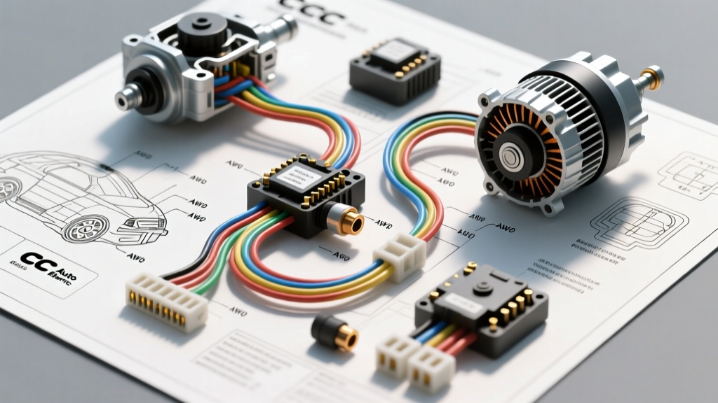
Introduction to CCC Auto Electric Components
When upgrading or replacing electrical components in commercial fleets, heavy-duty trucks, or high-draw passenger vehicles, selecting the right hardware is critical for long-term reliability. CCC Auto Electric has established a strong footprint in the global aftermarket, providing cost-effective, high-output alternators and gear-reduction starter motors. However, swapping OEM units for CCC Auto Electric equivalents requires a precise understanding of pinout configurations, wire gauge (AWG) requirements, and circuit load capacities. Improper integration of these components can lead to catastrophic voltage drops, PCM (Powertrain Control Module) damage, or chronic no-crank conditions.
This guide provides a comprehensive product comparison, wiring integration matrix, and technical installation specifications for CCC Auto Electric alternators and starter motors, ensuring your vehicle's electrical architecture meets or exceeds SAE J541 Heavy Duty Electrical Standards.
Product Comparison: CCC Auto Electric vs. Standard OEM
CCC Auto Electric primarily focuses on high-amperage, heavy-duty applications. When comparing their 12V 140A-170A alternator lineup against standard OEM equivalents (such as baseline Denso or Bosch units), several architectural differences emerge. CCC units frequently utilize 12-diode hairpin rectifier bridges compared to the standard 6-diode setups found in older OEM light-duty alternators. This design dissipates heat more efficiently and provides up to 30% more idle-output amperage, which is crucial for vehicles running auxiliary PTO (Power Take-Off) equipment, winches, or high-draw AC compressors.
Heavy-Duty Alternator Selection Matrix
| Specification | CCC Auto Electric 140A HD | Standard OEM 105A | Advantage / Application |
|---|---|---|---|
| Stator Winding | High-Density Copper (Hairpin) | Standard Round Wire | Higher slot fill, better thermal management |
| Rectifier Diodes | 12-Diode (Dual Rectifier) | 6-Diode Standard | Reduces ripple voltage, protects sensitive CAN-bus modules |
| Idle Output (600 RPM) | 95A - 105A | 45A - 55A | Essential for fleet vehicles with constant parasitic draws |
| Bearing Type | Sealed Heavy-Duty Roller | Standard Ball Bearing | Extended lifespan under high radial belt tension |
Alternator Wiring Integration & Pinout Configurations
Integrating a CCC Auto Electric 3-wire alternator into an existing harness requires strict adherence to terminal assignments. Unlike 1-wire setups that rely on internal sensing (which often leads to undercharging at the battery), CCC's 3-wire external sense configurations provide precise voltage regulation based on actual battery terminal voltage.
CCC 3-Wire Alternator Pinout & Routing Specs
| Terminal | Function | Wire Color (Typical) | Minimum AWG | Routing & Termination Rules |
|---|---|---|---|---|
| B+ | Main Battery Output | Red | 4 AWG (up to 120A) / 2 AWG (150A+) | Must route directly to battery positive or main distribution block. Use adhesive-lined heat shrink on ring terminals. |
| S (Sense) | Voltage Sense Input | Yellow or Orange | 14 AWG | Must connect directly to the battery positive post. Never splice into the B+ wire near the alternator. |
| L (Lamp/Ign)Exciter & Dash Lamp | White w/ Black Tracer | 18 AWG | Connect to ignition-switched 12V source via a 50-ohm resistor or parallel dash bulb to prevent backfeed. |
Critical Failure Mode Warning: If the 'S' (Sense) terminal wire is routed through a corroded firewall bulkhead connector, the voltage drop across the bulkhead will trick the alternator's internal regulator. The regulator will overcompensate by pushing 15.5V or higher into the system to satisfy the sense wire's low reading. This thermal runaway will boil battery electrolyte, destroy AGM separators, and potentially fry the vehicle's PCM. Always run a dedicated, fused 14 AWG sense wire directly to the battery terminal.
Starter Motor Circuit & AWG Sizing Requirements
CCC Auto Electric gear-reduction starters (typically rated between 3.0kW and 5.5kW for diesel and heavy gas applications) draw massive transient current. A 4.0kW starter operating at 12V can pull upwards of 350 Amps during initial lock-rotor engagement. Standard OEM battery cables are often undersized for these high-torque aftermarket units, leading to voltage collapse and solenoid chatter.
Voltage Drop & Cable Sizing Chart for CCC Starters
| Starter Rating | Peak Draw (Amps) | Max Cable Length (One Way) | Required B+ Cable AWG | Required Ground Cable AWG |
|---|---|---|---|---|
| 2.0kW - 2.5kW | 180A - 220A | Up to 6 feet | 2 AWG | 2 AWG |
| 3.0kW - 4.0kW | 280A - 350A | Up to 8 feet | 1/0 AWG | 1/0 AWG |
| 4.5kW - 5.5kW | 400A - 500A | Up to 10 feet | 2/0 AWG or 3/0 AWG | 2/0 AWG |
For the solenoid trigger wire (S-Terminal), do not rely on the factory 16 AWG ignition switch wire. The high magnetic coil resistance of heavy-duty CCC solenoids requires a solid 10 AWG or 12 AWG feed from a dedicated 30A starter relay. Using undersized wire for the S-terminal results in the solenoid pulling in but failing to engage the main starter contacts, causing a rapid 'clicking' noise and burning out the solenoid coil.
Installation Torque Specs & Grounding Best Practices
Proper mechanical installation is just as vital as electrical routing. Vibration in commercial and off-road vehicles will loosen improperly torqued high-amperage connections, leading to arcing, localized melting, and fire hazards. According to ISO 16750 Automotive Electrical Environmental Conditions, high-current terminations must withstand severe mechanical shock and thermal cycling.
Hardware Torque Specifications
- Alternator B+ Terminal (M8 Nut): 10 - 12 Nm (88 - 106 in-lbs). Over-torquing will strip the soft brass terminal stud.
- Alternator Sense/Lamp Terminals (M5 Nut): 3 - 4 Nm (26 - 35 in-lbs).
- Starter B+ Stud (M10 Nut): 25 - 30 Nm (18 - 22 ft-lbs). Use a hardened steel flat washer beneath the nut to prevent biting into the copper lug.
- Starter Mounting Bolts (M10 or M12): 45 - 55 Nm (33 - 40 ft-lbs). Apply medium-strength threadlocker (Blue) to prevent backing out due to engine harmonic vibration.
The 'Star Washer' Grounding Rule
When grounding a CCC Auto Electric starter or alternator to the engine block or chassis, never rely solely on the casting-to-bracket mating surface. Paint, powder coating, and aluminum oxidation act as dielectric insulators. You must install a dedicated braided copper grounding strap (minimum 2 AWG) from the starter housing directly to a clean, bare-metal point on the chassis. When securing ground lugs, always use a stainless steel internal-tooth star washer. The star washer bites through microscopic layers of corrosion and oxidation, ensuring a permanent, low-resistance path back to the battery negative terminal.
Troubleshooting Decision Tree: Post-Installation Issues
If you have installed a CCC Auto Electric component and are experiencing anomalies, follow this diagnostic sequence:
- Symptom: Battery voltage reads 14.8V+ at idle, battery is gassing.
Cause: Sense wire (S-terminal) is broken, disconnected, or reading a massive voltage drop.
Fix: Check continuity of the Yellow sense wire from the alternator plug directly to the battery positive post. - Symptom: Starter solenoid clicks rapidly, engine does not crank.
Cause: Voltage drop at the S-terminal trigger wire exceeds 3V during the crank attempt.
Fix: Install a 30A Bosch-style relay near the starter. Use the factory ignition wire to trigger the relay coil, and run a fresh 10 AWG wire from the battery to the relay, feeding the starter S-terminal. - Symptom: Alternator whining noise correlating with RPM, accompanied by headlight flickering.
Cause: Slipping serpentine belt due to incorrect tension, or mismatched pulley ratio.
Fix: Verify the CCC alternator pulley diameter matches the OEM unit. If the CCC unit has a smaller pulley for low-RPM output, ensure the automatic belt tensioner is not maxed out on its travel indicator.
Authoritative References
For further engineering data on heavy-duty electrical integration, consult the following resources: