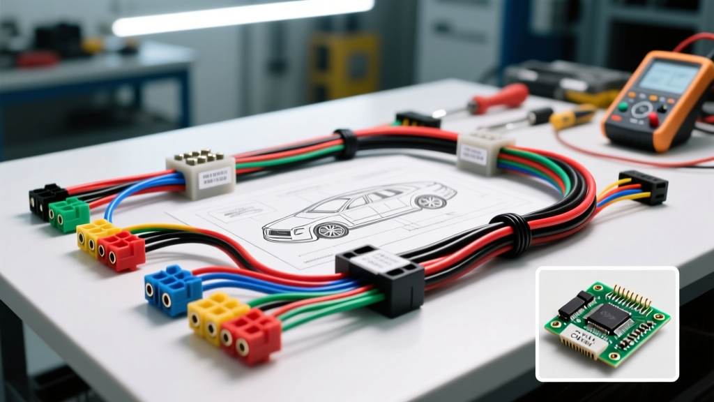
Introduction to Modern Auto Electricity and Electronics
Modern vehicles are no longer just mechanical machines with simple 12-volt accessories; they are rolling, high-speed data networks. Understanding auto electricity and electronics requires a fundamental shift from simple continuity testing to advanced network and signal analysis. Whether you are diagnosing a no-crank condition, tracking down a parasitic battery drain, or analyzing a Controller Area Network (CAN) bus fault, a systematic, step-by-step troubleshooting flow is mandatory to avoid misdiagnosis and unnecessary parts replacement.
This guide provides a master troubleshooting flow for the three most critical domains of automotive electrical systems: Power/Ground integrity, Data Network (CAN) diagnostics, and Parasitic Draw isolation. According to the National Institute for Automotive Service Excellence (ASE), over 60% of electrical comebacks are due to improper ground verification and failure to follow a structured diagnostic tree.
Phase 1: Power and Ground Circuit Integrity Flow
Before testing sensors, modules, or actuators, you must verify the integrity of the power supply and ground paths. A module cannot process logic if its foundation is compromised.
Step 1.1: Battery State of Charge (SOC) and Surface Charge
- Turn the ignition OFF and remove the key (or fob) from the vehicle.
- Connect a digital multimeter (DMM) to the battery posts (not the terminal clamps).
- Read the resting voltage. A fully charged AGM battery should read 12.7V - 12.9V; a standard flooded lead-acid battery should read 12.6V.
- Decision Node: If voltage is below 12.4V, charge the battery before proceeding. Low voltage causes modules to set false U-codes (network communication codes).
Step 1.2: Voltage Drop Testing the Ground Path
Never use an ohmmeter to test a ground circuit under load. Ohmmeters use less than 5 milliamps to test continuity, which will not reveal high-resistance failures like fretting corrosion inside a TE Connectivity MX150 connector.
- Set your DMM to DC Millivolts (mV).
- Place the red probe on the battery negative post and the black probe on the metal casing of the suspect component (e.g., starter motor housing, ECM bracket).
- Crank the engine or activate the high-load circuit.
- Specification: A healthy ground path will show a voltage drop of less than 0.10V (100mV) across the entire ground circuit, and less than 0.02V across a single connection point.
- Decision Node: If the drop exceeds 0.10V, isolate the circuit by moving the black probe closer to the battery (e.g., to ground stud G102 behind the left headlight) to find the exact point of resistance.
Phase 2: Data Network (CAN Bus) Diagnostics Flow
Modern auto electricity and electronics rely heavily on multiplexed networks. The High-Speed CAN (HS-CAN) bus operates at 500 kbps and is the backbone of powertrain and chassis communication. We will use the OBD-II Data Link Connector (DLC) as our primary access point.
Step 2.1: Visual and Pin Verification
Locate the 16-pin OBD-II DLC. Standard HS-CAN pins are Pin 6 (CAN-High)Pin 14 (CAN-Low). Inspect the female terminals for spread pins or corrosion, a common failure mode when aftermarket scan tools are repeatedly inserted.
Step 2.2: Static Resistance Check (Termination Resistors)
- Disconnect the vehicle battery negative cable to prevent module back-feed.
- Set the DMM to Ohms (Ω).
- Measure across DLC Pin 6 and Pin 14.
- Specification: You must read exactly 60 Ohms. This represents two 120-ohm terminating resistors (usually located in the ECM and TCM or instrument cluster) wired in parallel.
- Decision Node:
- Reading 120 Ohms: One termination resistor is open or missing (check module power/ground or internal module failure).
- Reading 0 Ohms: CAN-H and CAN-L are shorted together.
- Reading Infinite (OL): Both resistors are open, or the DLC pins are disconnected from the network.
Step 2.3: Active Voltage and Oscilloscope Analysis
Reconnect the battery and turn the ignition ON (engine OFF). According to SAE J1979 OBD-II standards, the bus must remain active for communication.
- CAN-High (Pin 6): Should rest between 2.6V and 3.5V.
- CAN-Low (Pin 14): Should rest between 1.5V and 2.4V.
- Oscilloscope Check: When transmitting data, CAN-H drives UP toward 3.5V, and CAN-L drives DOWN toward 1.5V. The signals should be perfect mirror images of each other. If both signals move in the same direction, the network is suffering from a short-to-ground or short-to-voltage on one of the legs.
Phase 3: Parasitic Draw Isolation Flow
A parasitic draw will destroy a battery in a matter of days. Modern vehicles with complex auto electricity and electronics architectures require up to 30 minutes to 'go to sleep' as modules sequentially shut down.
Step 3.1: The Fuse Voltage Drop Method (Non-Intrusive)
Breaking the circuit with a series ammeter can interrupt network wake-up signals and cause modules to reset, ruining your test. Instead, use the voltage drop method across the fuses.
- Ensure all doors are closed (use a latch tool or tape the door jamb switches), the hood latch is bypassed, and the key fob is at least 15 feet away.
- Wait 30-45 minutes for the vehicle to enter sleep mode.
- Set the DMM to DC Millivolts (mV).
- Probe the two exposed test points on the top of each MINI/ATO fuse in the interior and under-hood fuse boxes.
- Compare the mV reading to the fuse size using the chart below to calculate the amperage draw.
Reference Table: Fuse Voltage Drop to Amperage Conversion
| Fuse Rating (MINI) | mV Drop Reading | Calculated Amperage (Approx) | Status |
|---|---|---|---|
| 10 Amp | 1.0 mV | 0.12 A (120 mA) | Borderline / Suspect |
| 10 Amp | 2.5 mV | 0.30 A (300 mA) | FAIL (Excessive Draw) |
| 15 Amp | 0.8 mV | 0.15 A (150 mA) | Borderline / Suspect |
| 20 Amp | 0.5 mV | 0.18 A (180 mA) | Borderline / Suspect |
Note: Acceptable sleep-mode parasitic draw for modern vehicles is typically between 20mA and 50mA (0.02A - 0.05A). Consult manufacturer-specific service data, as some luxury vehicles with telematics modules may spec up to 80mA.
Step 3.2: Module Isolation
Once a circuit with excessive draw is identified via the fuse chart, consult the vehicle's wiring schematic to identify all modules on that specific fused circuit. Pull the connectors one by one (checking for terminal tension and moisture ingress, common in Delphi Packard Metri-Pack 280 connectors) until the draw drops. If the draw persists with all modules disconnected, the fault lies in the wiring harness (e.g., a chafed wire shorted to ground downstream of the fuse but upstream of the load).
Phase 4: Signal and Actuator Verification
Once power, ground, and networks are verified, you can test specific sensors and actuators. For Pulse Width Modulated (PWM) circuits, such as modern cooling fan modules or fuel pump control modules, a standard DMM will only show an 'average' voltage, which is highly misleading.
- Duty Cycle Testing: Use a DMM with a Duty Cycle (%) setting or an oscilloscope. A 50% duty cycle on a 12V PWM fan circuit will read ~6V on a standard DMM, but the scope will reveal a clean 0V to 12V square wave.
- Wire Color Codes: While DIN 72551 standardizes basic colors (Red = Constant 12V, Black = Ground, Green = Ignition Switched), signal wire colors vary wildly by manufacturer. Always rely on the specific OEM wiring diagram pinout rather than guessing by wire color.
Summary of Best Practices
Troubleshooting auto electricity and electronics requires patience, pristine test equipment, and adherence to the flow. Never pierce wires with test probes, as this compromises the insulation and invites capillary action moisture intrusion, leading to future green-death corrosion. Always back-probe connectors using proper terminal release tools and back-probe pins. For further reading on advanced network topologies and heavy-duty multiplexing, refer to the SAE J1939 documentation and Bosch Mobility Solutions technical literature.